
Gallery-mode microdisc system for electrically pumped optical sources

a microdisc and optical source technology, applied in the field of gallery-mode microdisc systems for electrically pumped optical sources, can solve the problems of small losses and partly limit the quality factor of contact, and achieve the effects of limiting the recombination of unnecessary carriers, effective pumping, and effective injection of carriers

Active Publication Date: 2010-03-11
CENT NAT DE LA RECHERCHE SCI +1
View PDF6 Cites 6 Cited by
  • Summary
  • Abstract
  • Description
  • Claims
  • Application Information

AI Technical Summary

Benefits of technology

[0012]The aim of the invention is to limit the recombinations of unnecessary carriers at the centre of the disc by modifying the electrical properties of the latter and the geometry or even the nature of the contact. The present invention thus makes it possible to effectively inject carriers in order to obtain more effective pumping and a lower laser threshold.
[0014]The protective layer has double role. It guarantees a sufficient index contrast with the index of the microdisc in order to confine the optical mode. It also makes it possible to encapsulate the whole of the structure in order to obtain a mechanically rigid system.

Problems solved by technology

Though optical pumping of such devices can easily be achieved the same does not apply with electrical pumping.
The presence of electrical contacts on the principal faces of the microdisc can cause sizeable losses due to their absorption in the infrared (or the working wavelength).
The latter solution is difficult to apply to the upper contact and the thickness left for the contact partly limits the quality factor.

Method used


Image

  • Gallery-mode microdisc system for electrically pumped optical sources
  • Gallery-mode microdisc system for electrically pumped optical sources
  • Gallery-mode microdisc system for electrically pumped optical sources

Examples


Embodiment Construction

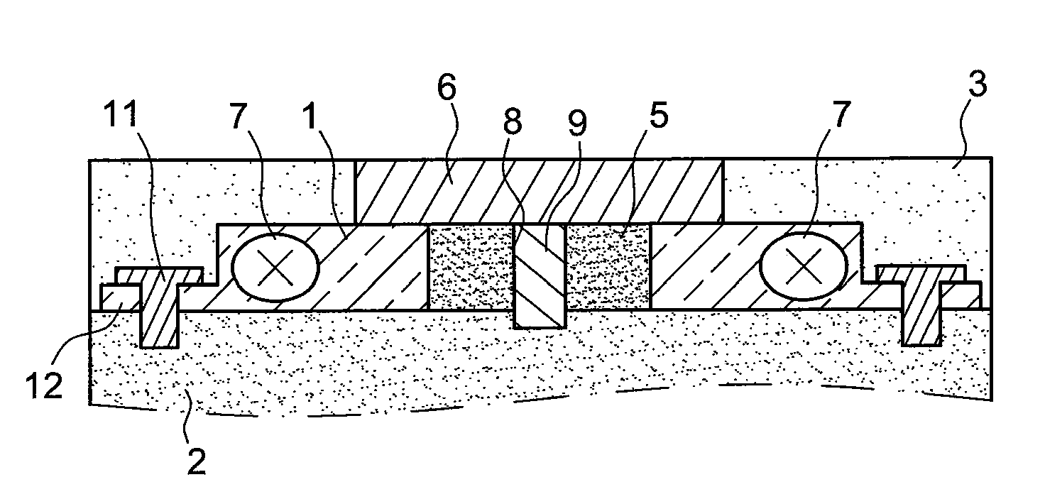
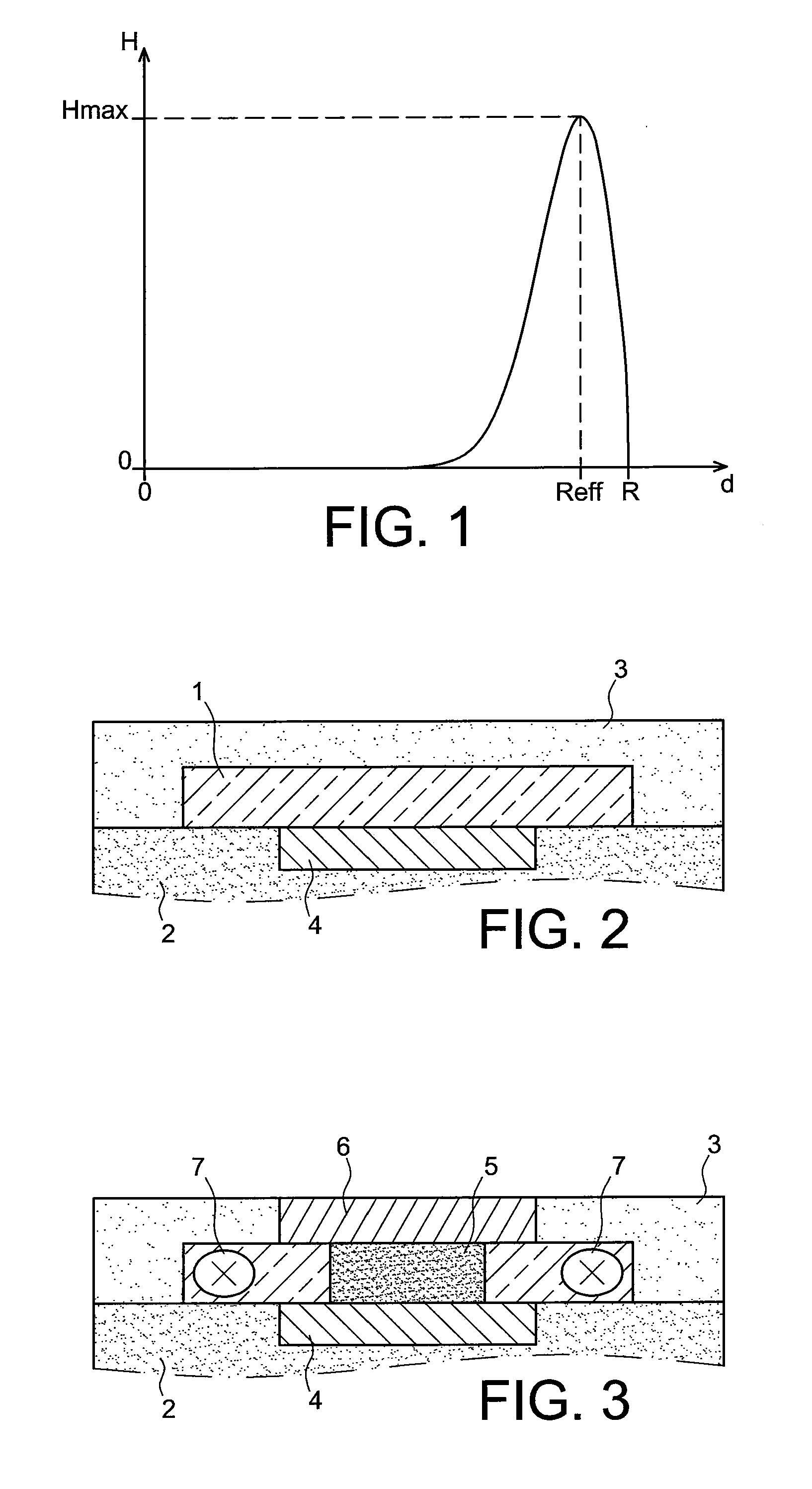
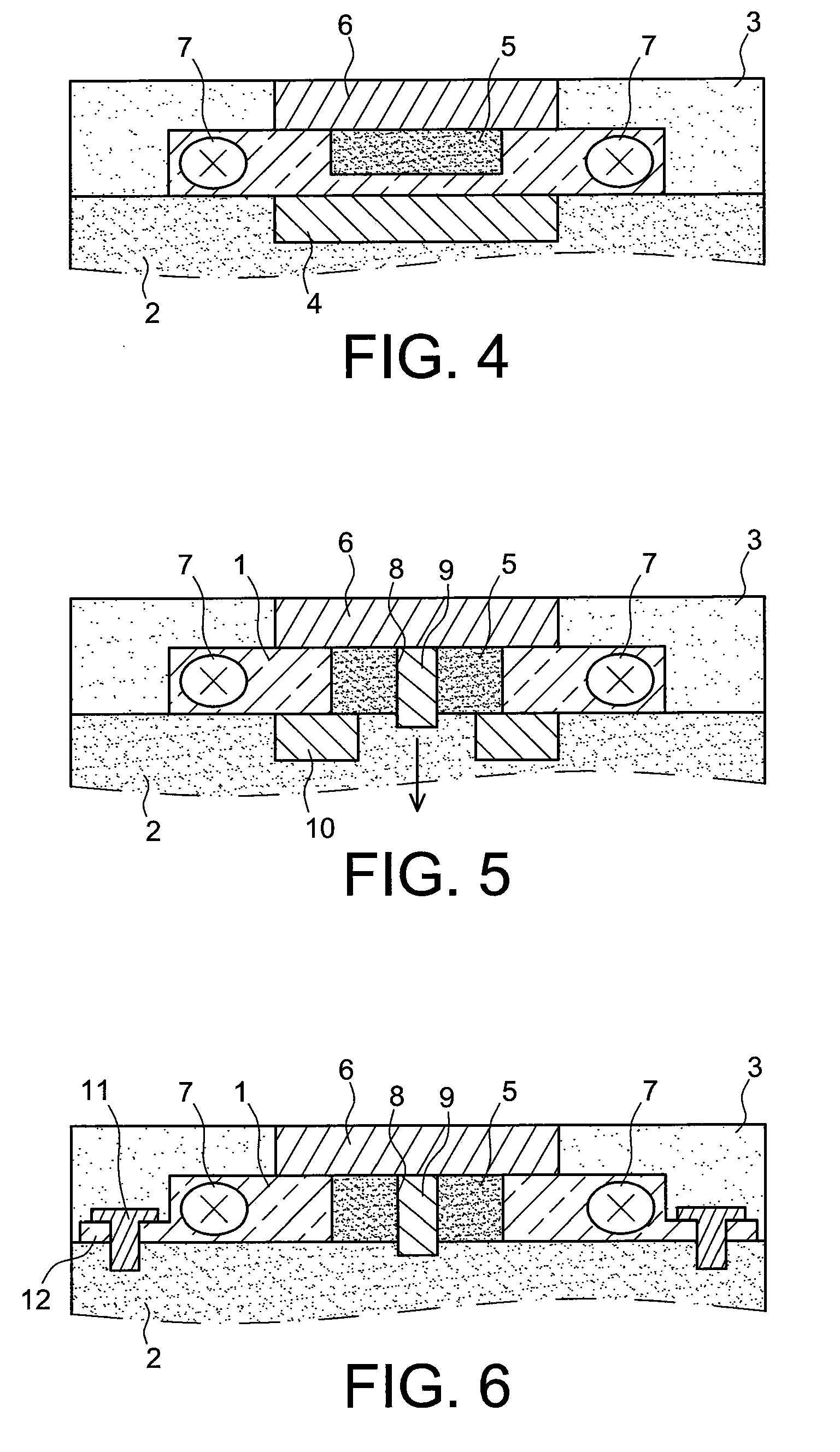
[0027]FIG. 2 is a view in transverse section of a microdisc on its supporting substrate during its production, according to the invention.

[0028]In FIG. 2, the reference 1 represents a microdisc, for example made from InP. The microdisc 1 is obtained by a technique known to persons skilled in the art. It is formed on a silicon substrate 2 (or on any other support used in microelectronics) covered with a layer of silicon oxide (or other electrically insulating material with a low refractive index). The lower and upper faces of the microdisc 1 comprise doped areas for obtaining an electrical contact with electrodes or contacts electrically connecting the faces of the microdisc with a current source.

[0029]The microdisc is covered with a protective layer 3 of material with a low optical index and electrically insulating. It is for example a layer of silica (SiO2) or nitride (Si3N4) or an SiOxNy compound deposited by vacuum deposition (PVD, PECVD, etc.) and with a thickness greater than o...


PUM


Abstract

The invention concerns a gallery mode microdisc system for an electrically pumped optical source, the microdisc (1) being formed on one face of a substrate (2), the lower part of the microdisc being provided with an electrical contact referred to as the lower contact (4), the upper part of the microdisc being provided with an electrical contact referred to as the upper contact (6), the upper part of the microdisc being covered with a protective layer (3) of electrically insulating material, the central part (5) of the microdisc being electrically neutralised in order to prevent the passage of an electric current in said central part.

Description

TECHNICAL FIELD[0001]The invention relates to gallery mode microdisc systems for electrically pumped optical sources. It concerns in particular the integration of the optics in electronic systems for generating optical signals.PRIOR ART[0002]Microlasers are known where the resonator consists of a microdisc or micro-ring. A microdisc or micro-ring resonator, using gallery modes (referred to “whispering gallery modes” in articles in English) makes it possible to obtain a high confinement of the photons. The same applies to a microresonator consisting of a microstructure based on photonic crystal with one or two dimensions.[0003]Gallery mode (GM) discs are characterised by electromagnetic modes complying with the geometry of revolution of the disc: the modes are therefore distinguished by their radial order (number of nodes on a radius), their azimuth order (the number of periods) and their vertical order (the number of nodes in the thickness of the disc). These discs are produced from...

Claims


Application Information

Patent Timeline
IPC IPC(8): H01S5/00H01S3/08
CPCH01S5/021H01S5/0218H01S5/1075H01S5/0424H01S5/0425H01S5/0422
Inventor MANDORLO, FABIENFEDELI, JEAN-MARCROJO-ROMEO, PEDRO
Owner CENT NAT DE LA RECHERCHE SCI
Learn More