Array of planar membrane modules for producing hydrogen

a planar membrane and hydrogen technology, applied in chemical/physical processes, catalyst activation/preparation, bulk chemical production, etc., can solve the problems of insufficient energy storage capacity of storage or rechargeable batteries, inability to provide compressed hydrogen, and safety issues involved in handling and storage of hydrogen, etc., to achieve high purity and low cost.

Inactive Publication Date: 2010-03-18
VENCILL THOMAS R +2
View PDF100 Cites 32 Cited by
  • Summary
  • Abstract
  • Description
  • Claims
  • Application Information

AI Technical Summary

Benefits of technology

[0010]The present disclosure describes a planar hydrogen separation membrane module that is capable of handling high temperatures typically associated with steam reforming environments (600-700° C. and pressures up to 200 psig) for production of high purity hydrogen. The membrane module is compact, lightweight, and scalable, uses low cost fabrication and assembly processes, and can be utilized in a variety of configurations inside membrane reformers, including an array configuration. The simultaneous realization of hydrogen production and hydrogen separation in a membrane reformer permits higher hydrocarbon conversions and hydrogen yields over that anticipated by thermodynamic equilibrium and over that anticipated by a process that involves hydrogen production and hydrogen separation in a sequential fashion.

Problems solved by technology

However, the amount of energy that can be stored in storage or rechargeable batteries is insufficient to meet the need of certain applications.
Merely providing compressed hydrogen is not always a viable option, because of the substantial volume that even a highly compressed gas occupies.
Furthermore, there are safety issues involved with the handling and storage of hydrogen in the compressed gas form or in the liquid form.
Methods such as water gas shift and preferential oxidation are used to reduce the CO concentrations to acceptable levels of no more than 50 parts per million, but increase the complexity of the system.

Method used


Image

  • Array of planar membrane modules for producing hydrogen
  • Array of planar membrane modules for producing hydrogen
  • Array of planar membrane modules for producing hydrogen

Examples


example 1

Hydrogen Flux Through a Reformer Sub Assembly in which the Membrane is Supported on a Sintered Porous Metal Substrate

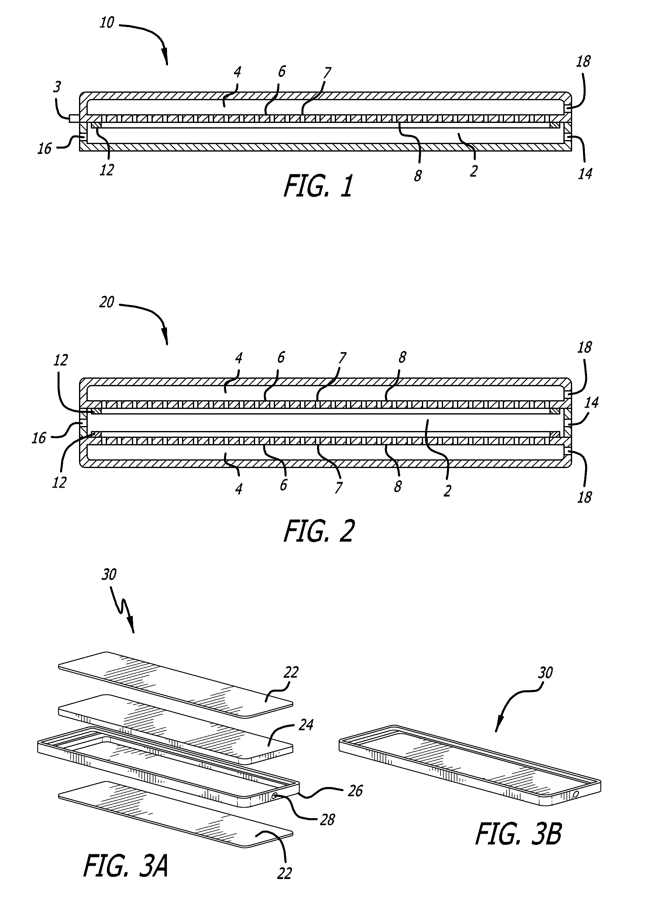
[0145]A gas mixture consisting of hydrogen and nitrogen in the nominal volumetric ratio of 75% H2 and 25% N2 and at a nominal flow rate of 1500 sccm was fed into a reaction chamber as shown in FIG. 1 after heating the chamber to about 450° C. The reaction sub assembly was constructed of SS 304. The membrane consisted of a Pd / Ag foil of nominal composition 75% Pd / 25% Ag and had a surface area of 23 cm2.

[0146]The membrane foil, 25 microns in nominal thickness, was supported on a sintered porous stainless steel 316L substrate that possessed a nominal porosity of 41% (Mott Corp). The reactor sub assembly was placed in a Watlow electrical furnace which allowed for increasing the temperature of the furnace using a suitable temperature controller (Omega). The reaction chamber contained a 40 ppi FeCrAlY metal foam substrate to provide uniform flow and heat distribution.

[0147]...

example 2

Hydrogen Flux Through a Reactor Sub Assembly in which the Membrane was Supported on a Solid Plate Containing Perforations

[0149]The test as described in Example 1 was repeated using reactor sub assemblies that were identical to that used in Example 1, except for the fact that the membrane foil was supported on a solid SS 304 plate that contained small evenly spaced holes 1 / 32″ diameter with a total exposed surface area of 0.23 in2. In particular, hydrogen flux (sccm / cm2) was passed at 600° C. and at a nominal pressure of 5.8 bar through two identically construed Units 1 and 2, at various temperature cycles. Each temperature cycle was between ambient temperature and 600° C.

[0150]The pressure on the permeate side of the membrane was maintained at atmospheric pressure. The results reported in FIG. 27 show an approximately 30% decrease in hydrogen flux was observed with time. The membrane was found to be very stable to thermal cycling between ambient temperature and 600° C., as no decrea...

example 3

Hydrogen Flux Through a Reactor Sub Assembly in which the Membrane was Supported on a Sintered Porous Substrate

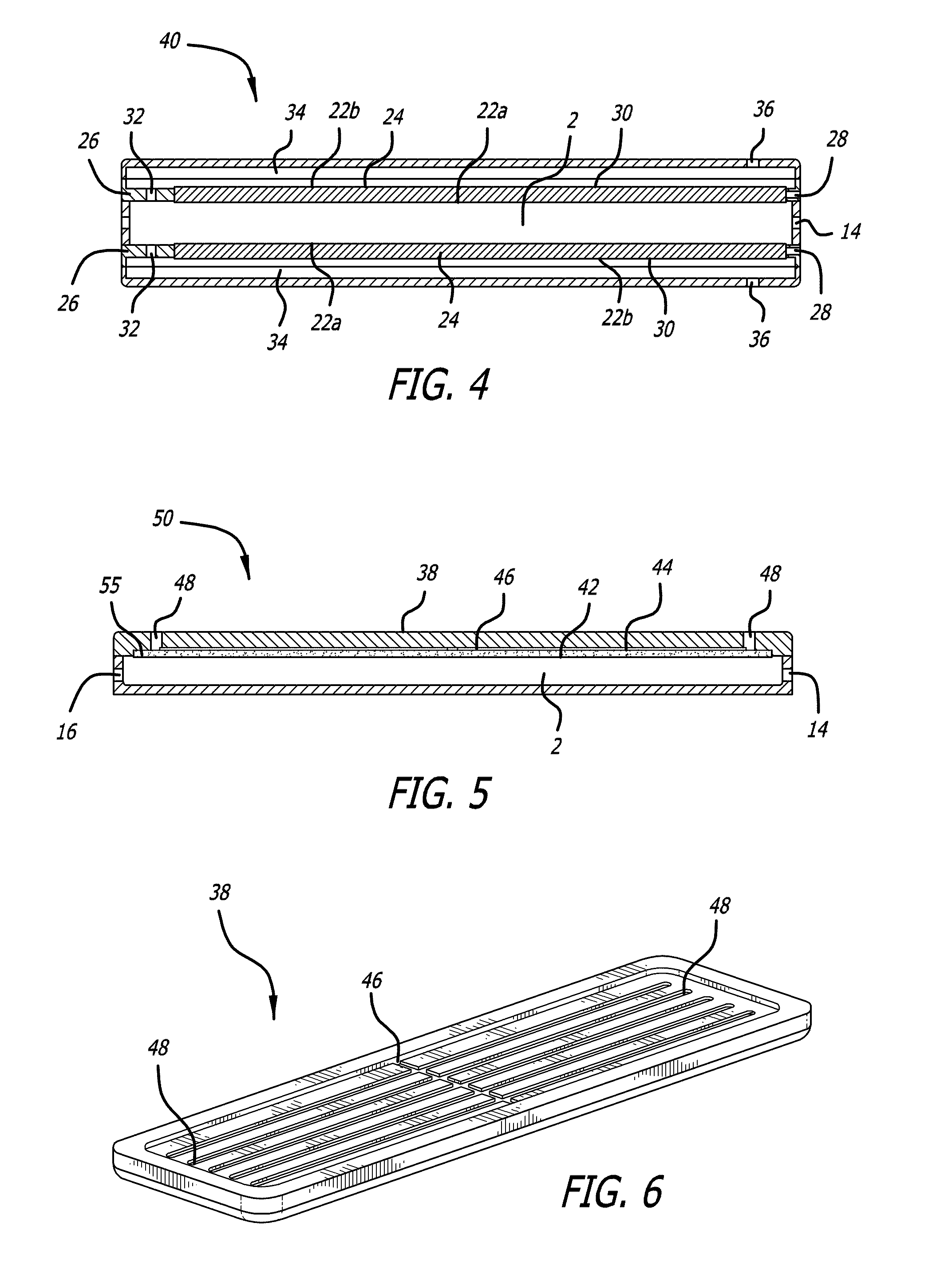
[0151]The substrate also behaved as a flow channel for transport of hydrogen to the exit ports of the device.

[0152]A gas mixture consisting of hydrogen and nitrogen in the nominal volumetric ratio of 75% H2 and 25% N2 and at a nominal flow rate of 3600 sccm was fed the reactor sub assembly as shown in FIG. 5 after heating the reactor to about 450° C. The reactor sub assembly was constructed of 304L stainless steel. The membrane consisted of a Pd / Ag foil of nominal composition 75% Pd / 25% Ag and had a surface area of 55 cm2. The membrane foil was supported on a sintered porous 316 stainless steel substrate that possessed a nominal porosity of 41% (Mott Corp). The membrane reactor was placed in a Watlow electrical furnace which allowed for increasing the temperature of the furnace using a suitable temperature controller (Omega). The reaction chamber contained a 40 ppi Inconel®...


PUM

PropertyMeasurementUnit
thicknessaaaaaaaaaa
thicknessaaaaaaaaaa
thicknessaaaaaaaaaa

Abstract

A shared or common environment membrane reactor containing a plurality of planar membrane modules with top and bottom thin foil membranes supported by both an intermediary porous support plate and a central base which has both solid extended members and hollow regions or a hollow region whereby the two sides of the base are in fluid communication. The membrane reactor operates at elevate temperatures for generating hydrogen from hydrogen rich feed fuels.

Description

RELATED APPLICATIONS[0001]This application is a continuation-in-part of U.S. application Ser. No. 11 / 109,186, filed on Apr. 18, 2005 which is a continuation-in-part and which is a continuation-in-part of U.S. application Ser. No. 10 / 476,015 entitled “Hydrogen Generation Apparatus And Method For Using Same”, which is a national phase filing of PCT International Application No. PCT / US02 / 12822, filed on Apr. 23, 2001, all of which are herein incorporated by reference in their entirety.STATEMENT REGARDING FEDERALLY SPONSORED RESEARCH OR DEVELOPMENT[0002]The disclosure was partly made with Government support under contract No. DE-FG36-07G017013 by the Department of Energy. The Government has certain rights in the disclosure.BACKGROUND[0003]This disclosure relates to hydrogen generating reactors and to hydrogen separation membranes.DESCRIPTION OF RELATED ART[0004]The growing popularity of portable electronic devices has produced an increased demand for compact and correspondingly portable...

Claims


Application Information

Patent Timeline
Patent Type & Authority Applications(United States)
IPC IPC(8): C01B3/02B01D53/22B23K26/00
CPCB01J19/0093Y02E60/364B01J35/04B01J37/0225B01J2219/00783B01J2219/00822B01J2219/00824B01J2219/00835B01J2219/00873B01J2219/00907B01J2219/2453B01J2219/2458B01J2219/246B01J2219/2462B01J2219/2466B01J2219/2467B01J2219/2475B01J2219/2479B01J2219/2486B01J2219/2497C01B3/047C01B3/323C01B3/384C01B3/505C01B2203/0233C01B2203/041C01B2203/0445C01B2203/047C01B2203/066C01B2203/0811C01B2203/0822C01B2203/0827C01B2203/1029C01B2203/1082C01B2203/1217C01B2203/1247C01B2203/1288B01J19/249Y02E60/36Y02P20/10Y02P20/52
Inventor VENCILL, THOMAS R.CHELLAPPA, ANAND S.RATHOD, SHAILENDRA B.
Owner VENCILL THOMAS R
Why Eureka
Try Eureka