Method for detection and analysis of aromatic hydrocarbons from water

Inactive Publication Date: 2010-03-18
DAKOTA TECH
View PDF15 Cites 43 Cited by
  • Summary
  • Abstract
  • Description
  • Claims
  • Application Information

AI Technical Summary

Benefits of technology

[0025]The present invention provides a simple, field-portable method to determine total dissolved aromatic hydrocarbon concentrations in water, including turbid fluids,

Problems solved by technology

Detection and/or measurement of aromatic hydrocarbons including polycyclic aromatic hydrocarbons (PAHs) and monocyclic aromatic hydrocarbons (MAHs), considered contaminants in the environment and other analytes of interest in a fluid sample matrix, can be difficult.
Many aromatic hydrocarbons are in forms that are not easily detected, or are dispersed in matrices or media that are unfit for field-work analysis, particularly for laser induced fluorescence (LIF) analysis.
For example, PAHs in coal tar and creosote are difficult to detect spectroscopically in their customary soil or water environment, because they may not fluoresce well in such media.
PAHs present in murky water, sediments or soils are unsuitable for LIF or similar optical analysis.
In addition to the increasing recognition that direct pore water measurements are needed to predict the bioavailability of sediment PAHs, it is becoming apparent that the conventional parent PAHs measured by EPA method 8270 (PAH-16) are not sufficient to represent potential PAH biological effects.
Therefore, these methods tend to retain many of the time and cost disadvantages of collecting sediment samples and shipping them to the laboratory for pore water analysis.
Unfortunately, the success of LIF to determine PAH concentrations has been limited by background spectral interferences from natural dissolved organic matter (DOM).
Chemosphere 1995, 31, 3345-3356), but this requires separation of the sediment and pore water, and is not practical in situ (embedded directly into the sediment) in the field.
However, thermal desorption processes destroy the environmental sample, and a single test of a selected sample may

Method used


Image

  • Method for detection and analysis of aromatic hydrocarbons from water
  • Method for detection and analysis of aromatic hydrocarbons from water
  • Method for detection and analysis of aromatic hydrocarbons from water

Examples


Embodiment Construction

[0083]In the specification and in the claims, the terms “including” and “comprising” are open-ended terms and should be interpreted to mean “including, but not limited to . . . .” These terms encompass the more restrictive terms “consisting essentially of” and “consisting of.”

[0084]The term environmental location refers to various man-made and natural fluid handling structures such as channels, trenches, troughs, tubing, and pipelines designed to hold, direct, and transport water, slurries, and muds in plants, factories, processing facilities, and natural waterways, including underground waterways. The fluid handling structures could be contained within municipal waste water plants, for transporting produced waters from oil and gas production facilities or sewage treatment facilities, stormwater runoff drain systems, and natural waterways including urban surface waters (rivers, bays, estuaries), including the sediments of natural surface waters or groundwater.

[0085]The term sediment...


PUM


Abstract

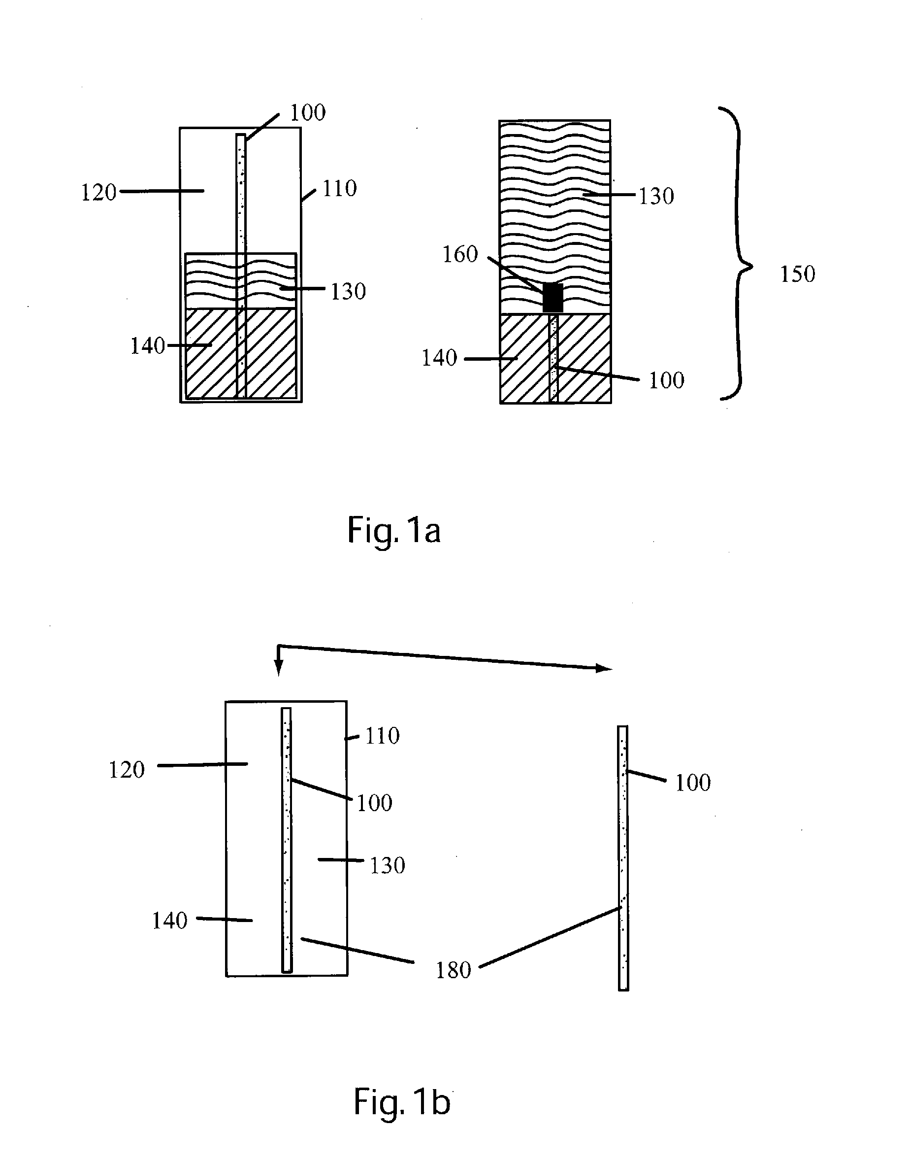
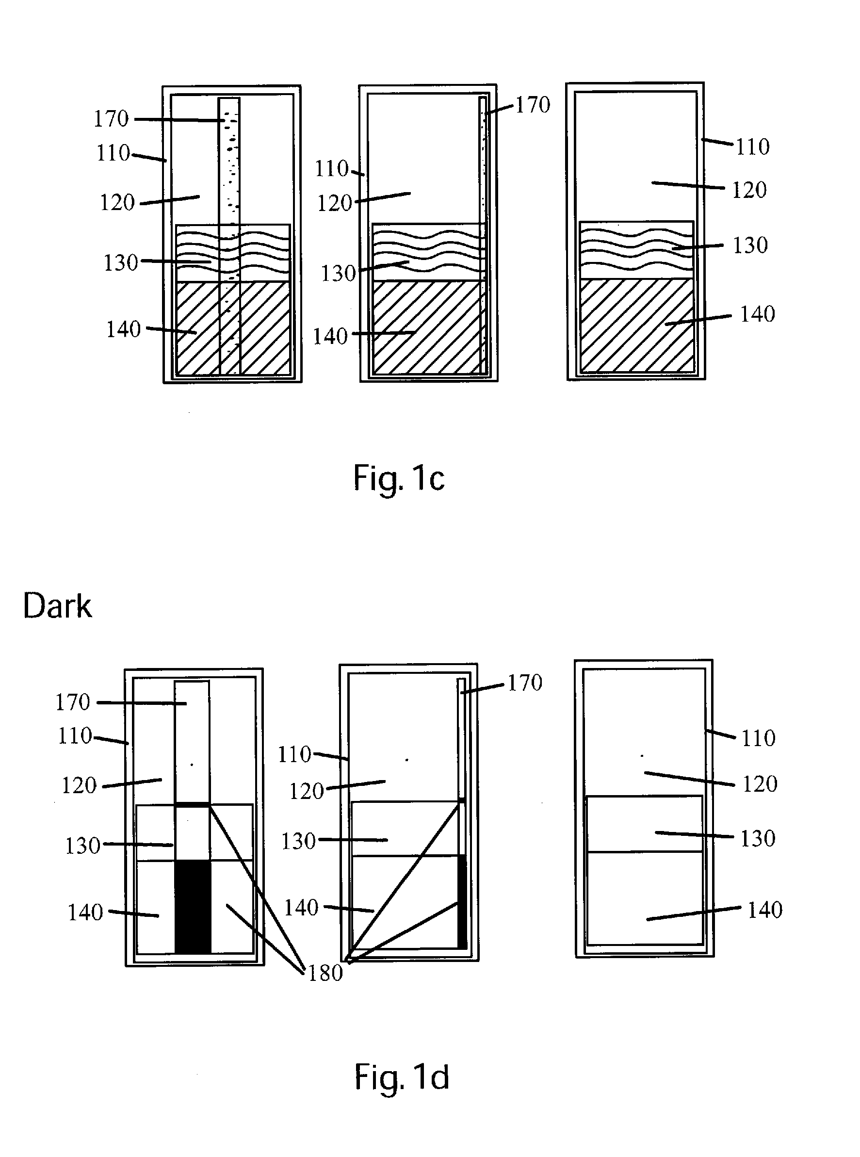
Methods for analyzing aromatic hydrocarbons dissolved in water are discussed. The methods include providing a substrate coated with a thin film layer of a material, wherein the material has a high affinity for at least one aromatic hydrocarbon, the material is substantially optically transparent, and the material has near-zero auto fluorescence, inserting the coated substrate directly into an environmental location including water, waiting for an exposure time permitting at least one aromatic hydrocarbon to absorb into the thin film layer, retrieving the coated substrate from the environmental location, removing any non-absorbed matter from the coated substrate, and performing fluorescence analysis on the coated substrate to detect aromatic hydrocarbons present in the thin film layer. Also methods for analyzing aromatic hydrocarbons dissolved in water contained in coated vessels are provided.

Description

CROSS REFERENCE TO RELATED APPLICATIONS[0001]This application claims priority to prior U.S. Provisional Application No. 61 / 096,508, filed Sep. 12, 2008, which is incorporated herein by reference.FIELD OF THE INVENTION[0002]The present invention relates generally to facilitating testing for environmental contaminants or other analytes by extracting from an environmental location, or from a fluid sample matrix, analytes present in trace amounts using a thin film layer of material for which the analytes of interest have a high affinity and that is substantially optically transparent and has a near-zero autofluorescence, then subjecting the thin film material with captured analytes to laser induced fluorescence (LIF) or other testing.BACKGROUND OF THE INVENTION[0003]Detection and / or measurement of aromatic hydrocarbons including polycyclic aromatic hydrocarbons (PAHs) and monocyclic aromatic hydrocarbons (MAHs), considered contaminants in the environment and other analytes of interest i...

Claims


Application Information

Patent Timeline
IPC IPC(8): G01N33/00
CPCY10T436/212G01N33/1826
Inventor ST. GERMAIN, RANDY
Owner DAKOTA TECH
Why Eureka
Try Eureka