Ultrasonic diagnostic apparatus and computer program product

a diagnostic apparatus and ultrasonic technology, applied in the field of ultrasonic diagnostic equipment and computer program products, can solve the problems of reduced scan rate, loss of realtime responsiveness, and large stress on a subject, and the burden on an operator tends to be larg

Active Publication Date: 2010-03-18
TOSHIBA MEDICAL SYST CORP
View PDF6 Cites 50 Cited by
  • Summary
  • Abstract
  • Description
  • Claims
  • Application Information

AI Technical Summary

Benefits of technology

[0024]According to one aspect of the present invention, an ultrasonic diagnostic apparatus includes a region-of-interest setting unit that sets a region of interest to be included in an ultrasound image created based on reception data acquired by using an ultrasonic wave reflected from a subject; an inter-reception-data movement-amount calculating unit that calculates a movement amount of the region of interest set by the region-of-interest setting unit between reception data along a time sequence acquired by using an ultrasonic wave reflected from the subject, as an inter-reception-data movement amount; a scan-region control unit that controls a scan region of an ultrasonic wave to be transmitted from an ultrasonic probe such that the scan region is to be shifted based on the inter-reception-data movement amount calculated by the inter-reception-data movement-amount calculating unit; an image creating unit that creates a plurality of ultrasound images along a time sequence based on reception data corresponding to an ultrasonic wave transmitted from the ultrasonic probe into the scan region shifted according to control by the scan-region control unit; and a display control unit that controls a display such that the ultrasound images along the time sequence created by the image creating unit are displayed on a predetermined display unit.

Problems solved by technology

Therefore, if scanning density is increased to improve the image quality of an ultrasound image, a scan rate that is the number of scan lines per unit time is decreased, so that realtime responsiveness is lost.
According to the conventional technology described above, when the region of interest moves, there is a problem that a stress on a subject and a burden on an operator tend to be large in order to achieve both image-quality improvement and realtime responsiveness of an ultrasound image.
In this way, when a region of interest moves, a scan region is widened to ensure that the region of interest is to be included in an ultrasound image as well as to improve the image quality, the number of scan lines tends to increase, as a result, realtime responsiveness tends to be lost.
However, “to hold the breath” is not generally easy for a subject, and it is a difficult action particularly for a subject who has a respiratory disease or a subject of a relatively high age.
Consequently, in order to avoid stress on the subject, the operator has to continue manually operating the ultrasonic probe in accordance with the breath of the subject for the region of interest to be included in the ultrasound image; however, when creating a tomogram by using a one-dimensional ultrasonic probe, it is not an easy operation to continue adjusting the position of the one-dimensional ultrasonic probe for a moving region of interest to be included in the tomogram, thereby increasing a burden on the operator.
Moreover, even though the position of the ultrasonic probe is adjusted, it cannot be ensured that a moving region of interest is to be constantly included in a three-dimensional ultrasound image, consequently, the subject sometimes needs “to hold the breath” in some cases in order to avoid repeating a scan.
Furthermore, generally, a created three-dimensional ultrasound image is scarcely used as it is, and the operator cuts out a cross section that includes the region of interest from a three-dimensional ultrasound image, and then performs a diagnosis by referring to the cut out cross section; therefore, when performing a diagnosis by creating a three-dimensional ultrasound image, a burden on the operator becomes large.

Method used


Image

  • Ultrasonic diagnostic apparatus and computer program product
  • Ultrasonic diagnostic apparatus and computer program product
  • Ultrasonic diagnostic apparatus and computer program product

Examples


first embodiment

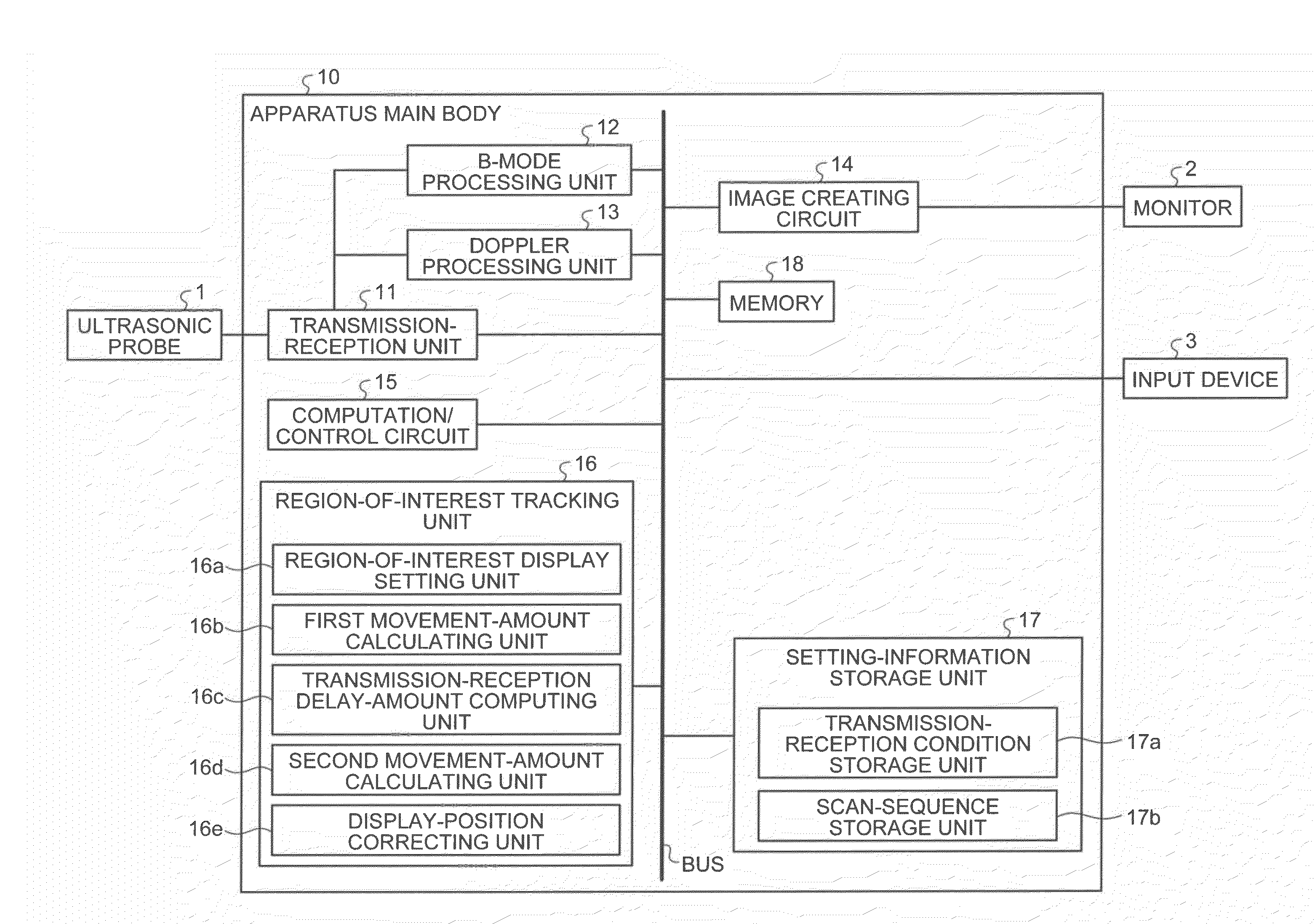
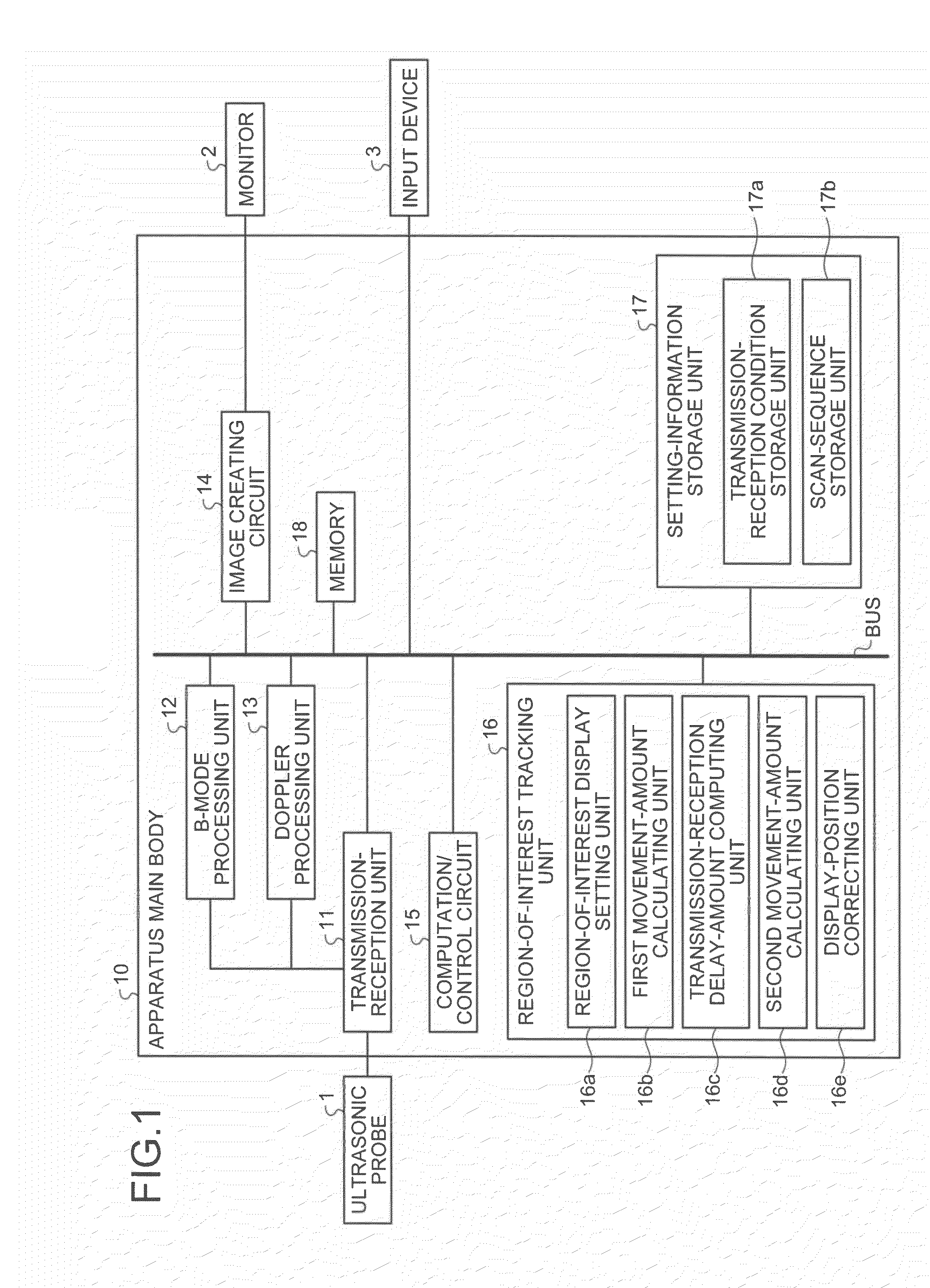
[0046]The B-mode processing unit 12 and the doppler processing unit 13 can process both two-dimensional data and three-dimensional data, and perform data creation processing for image composition based on three-dimensional reception data created from a three-dimensional reception signal received by the ultrasonic probe 1 that is a two-dimensional ultrasonic probe, according to the

[0047]The image creating circuit 14 creates a B-mode image, a doppler image, or a superposed image of a B-mode image and a doppler image, by performing transformation process into a rectangular coordinate system (orthogonal transformation process) and digital-to-analog (D / A) conversion process on data for image composition received from the B-mode processing unit 12 or the doppler processing unit 13, and the created image is displayed on the monitor 2. The B-mode processing unit 12, the doppler processing unit 13, and the image creating circuit 14 correspond to “an image creating unit” described in the clai...

second embodiment

[0131] processing of creating data for B-mode image composition is performed in a separated manner by two systems, namely, the first B-mode processing unit 12a and the second B-mode processing unit 12b.

[0132]In other words, the first B-mode processing unit 12a includes a filter that separates a fundamental wave for extracting data dominated by living-body tissue signals from reception data created by the transmitting-receiving unit 11; and the second B-mode processing unit 12b includes a filter that separates a subharmonic wave or a higher harmonic wave for extracting data dominated by contrast agent signals from reception data created by the transmitting-receiving unit 11.

[0133]As shown in FIG. 10, the first B-mode processing unit 12a extracts a fundamental wave that is a signal from a living body tissue through a receiving filter included in the first B-mode processing unit 12a, and creates data for B-mode image composition from the extracted fundamental wave. The fundamental wav...


PUM


Abstract

A region-of-interest setting unit sets a region of interest to be included in an ultrasound image. A first movement-amount calculating unit sequentially calculates a movement amount of the set region of interest between reception data along the time sequence as a first movement amount. A transmitting-receiving delay-amount computing unit computes a delay amount for sequentially shifting a scan region of an ultrasonic beam based on the sequentially calculated first movement amount. A computation/control circuit performs control so as to generate a high voltage pulse based on the computed delay amount. A second movement-amount calculating unit sequentially calculates a movement amount of the region of interest between image data along the time sequence as a second movement amount. A display-position correcting unit performs a correction such that the region of interest included in the image data is to be displayed at the same display position, based on the second movement amount.

Description

CROSS-REFERENCE TO RELATED APPLICATIONS[0001]This application is based upon and claims the benefit of priority from the prior Japanese Patent Application No. 2008-237661, filed on Sep. 17, 2008; the entire contents of which are incorporated herein by reference.BACKGROUND OF THE INVENTION[0002]1. Field of the Invention[0003]The present invention relates to an ultrasonic diagnostic apparatus and a computer program product.[0004]2. Description of the Related Art[0005]Conventionally, an ultrasonic diagnostic apparatus has advantages, such as simple and easy operability and noninvasiveness without risk of radiation exposure, compared with other medical image diagnostic apparatuses, for example, an X-ray diagnostic apparatus and an X-ray Computed Tomography (CT) apparatus; and is used in a medical practice of today for an examination or a diagnosis of the condition of a tissue among various living body tissues, for example, a heart, a liver, a kidney, a mammary gland, or a muscle.[0006]An...

Claims


Application Information

Patent Timeline
Patent Type & Authority Applications(United States)
IPC IPC(8): A61B8/14G06K9/00
CPCA61B5/4244A61B8/08A61B8/13A61B8/483G01S15/8993G01S7/52039G01S7/52063G01S7/52085A61B8/54
Inventor OGASAWARA, YOICHIOOMORI, YOSHIHIROAKAKI, KAZUYANAKAJIMA, OSAMU
Owner TOSHIBA MEDICAL SYST CORP
Why Eureka
Try Eureka