Aerogel-Based Filtration of Gas Phase Systems

a technology of gas phase system and aerogel, which is applied in the direction of filtration separation, liquid degasification, separation process, etc., can solve the problems of filter blockage, filter clogging, and high pressure drop with increasing loading, and achieve low pressure drop, high capacity, and high efficiency

Inactive Publication Date: 2010-03-25
NEW JERSEY INSTITUTE OF TECHNOLOGY
View PDF25 Cites 19 Cited by
  • Summary
  • Abstract
  • Description
  • Claims
  • Application Information

AI Technical Summary

Benefits of technology

[0017]The invention has many advantages. Practicing the invention is particularly useful in removing submicron particles and / or oil droplets. In some embodiments, it can replace existing HEPA filters, providing reliable filtration with high efficiency, high capacity and low pressure drop. Filters of the invention are expected to perform as well or better than HEPA filters with respect to pressure drop.
[0018]Compared with conventional HEPA filters, the invention reduces or minimizes the need for cleaning and / or replacing the filter.

Problems solved by technology

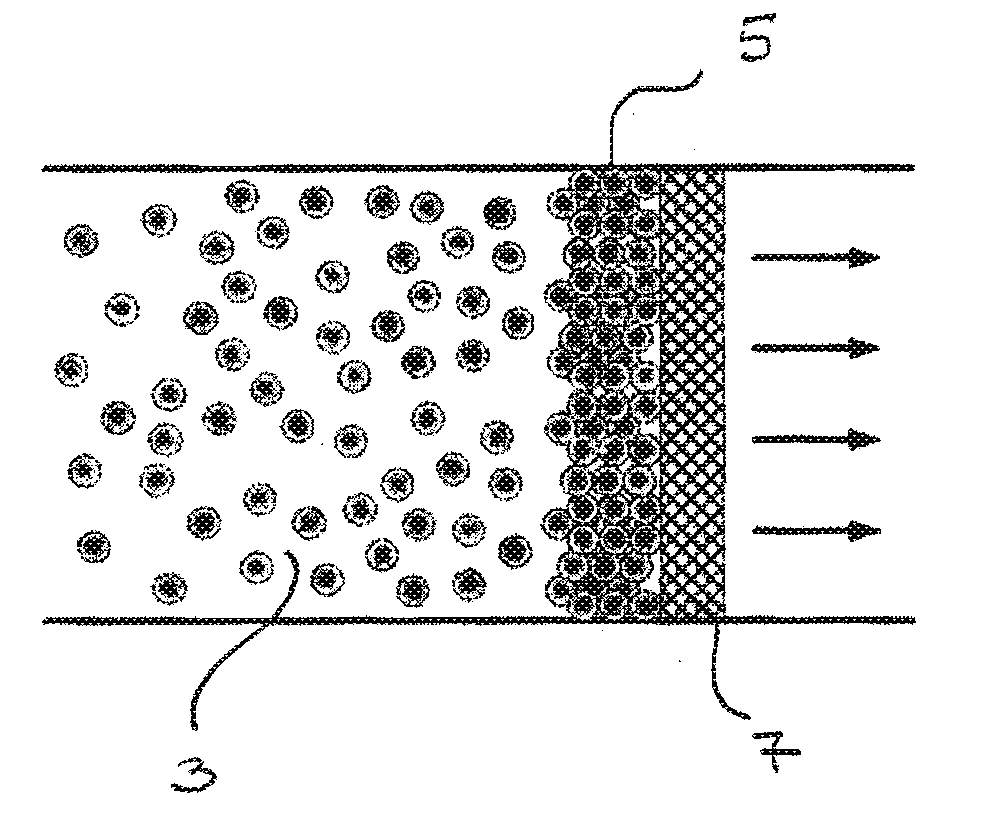
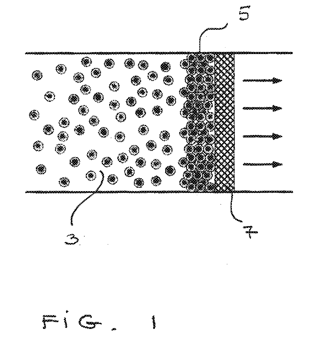
However, as the dendrites begin to fill the spaces between the fibers, a filter cake of increasing thickness begins to form at the upstream surface of the filter and the slope of the pressure drop with increasing loading rises sharply, indicating that the filter is being clogged.
However, the resistance of the filter increases, limiting the operative life of the filter.
Thus “surface” or “cake” filtration has good collection efficiency, low capacity and is accompanied by a rapid increase in pressure drop as the surface gets clogged.
However, as soon as the upstream surface becomes heavily clogged, filtration only occurs at the filter's surface, a phenomenon known as “cake filtration”, leading to a sharp rise in pressure drop.
Based on this sharp rise in pressure drop, filtration performance becomes unacceptable and the filter needs to be cleaned or replaced.
In typical fiber-based HEPA filters, this degradation in performance occurs at a loading of about 1 to 10 g / m2 of filter area.
MPPS oil droplets tend to coalesce and penetrate voids in conventional HEPA filters.
Whereas, due to cake formation over the surface of the filter, collection efficiency of HEPA filter can actually increase when challenged with solid particles, the collection efficiency for oil droplets tends to decrease with time, due to a reduction in fiber surface available for capturing incoming droplets, as the fibers become coated with liquid.
As with fiber-based HEPA filters these approaches do not appear to be very effective in handling submicron size droplets.

Method used


Image

  • Aerogel-Based Filtration of Gas Phase Systems
  • Aerogel-Based Filtration of Gas Phase Systems
  • Aerogel-Based Filtration of Gas Phase Systems

Examples


examples

[0106]Experiments described below were conducted using a set-up arrangement identical or similar to that shown in FIG. 7. Shown in FIG. 7 is apparatus 200, which included a clean air source, an aerosol generation system composed of atomizer 210 for the generation of submicron size droplets or the atomization of a suspension containing submicron solid particles such as polystyrene latex spheres (PSLS), drier 212 for removal of the solvent that contained the solid or liquid particles. Also included was particle counter system 214 located upstream of the filters. It included a Condensation Particle Counter (CPC) and a Scanning Mobility Particle Sizer (SMPS). A CPC 216 also was provided at diluter 218.

[0107]The atomizer was used to disperse solid polystyrene latex spheres (PSLS). A suitable Scanning Mobility Particle Sizer (SMPS) classified particles in the range of 15 to 800 nanometers, while Condensation Particle Counters (CPC) can count particles in the range of 0.015 microns to 2 mi...

example 1

[0128]Customized filters made of aerogel particles available from Cabot Corporation, Billerica, Mass. under the tradename of Nanogel®, were first challenged against submicron oil droplets. In FIG. 9A, the number collection efficiency of packed filters is plotted against the particle size of the challenging aerosol. As seen in the plot, at low at low gas velocities the collection efficiencies of packed beds of Nanogel® performed well. In particular, the packed bed of Nanogel® granules with sizes between 150-250 microns, 3 inches in depth (solid line A), showed an almost 100% collection efficiency. Two Nanogel® formulations were tested: Nanogel I corresponded to a translucent grade (TLD) and Nanogel II corresponded to an opaque grade (OGD). No significant difference between the two was observed in the air filtration experiments.

[0129]Fluidized beds of Nanogel® particles of sizes below 150 microns also were tested against oil droplets and FIG. 9B shows the collection efficiency of flui...

example 2

[0132]Customized filter modules also were challenged against submicron solid particles, specifically PSLS with nominal size of 0.3 microns. FIG. 10A shows the collection efficiency of packed filter modules of 3 inches in depth made of granules of different sizes as detailed in the legend of the figure. It can be seen that at low gas velocities, the customized filters showed acceptable collection efficiencies. The module containing granules in the range of 150-250 microns gives a collection efficiency of about 99.9% (solid line A), which is an improvement over HEPA filters.

[0133]Fluidized beds of Nanogel® aerogel, were challenged against submicron particles generated by atomizing PSLS with a nominal size of 0.3 microns. The collection efficiency of the fluidized beds is shown in FIG. 10B indicating that performance of the fluidized bed for capturing submicron particles was comparable to HEPA filters.


PUM

PropertyMeasurementUnit
droplet sizeaaaaaaaaaa
particle sizeaaaaaaaaaa

Abstract

A purification method comprises directing a system having a gas phase component and a contaminant through a filter including an aerogel material, e.g., hydrophobic silica-based aerogel particles. A filter for purifying a gas phase system comprises an aerogel material in an amount sufficient to remove at least a portion of a contaminant present in the gas phase system. In preferred examples, the filter is a fluidized bed. In further examples, the filter is a packed bed.

Description

RELATED APPLICATIONS[0001]This application is a Continuation of International Application Number PCT / US2007 / 083177, filed on 31 Oct. 2007, designating the United States, which claims the benefit under 35 USC 119(e) of U.S. Provisional Application No. 60 / 863,866, filed on Nov. 1, 2006, both of which are incorporated herein by reference in their entirety.GOVERNMENT SUPPORT[0002]The invention was made with government support from the National Science Foundation under Government Grant / Contract No. NSF NER BES 0507936 awarded by the National Science Foundation. The government has certain rights in the invention.BACKGROUND OF THE INVENTION[0003]Air filters with particularly high collection efficiency are generally referred to as High Efficiency Particulate Air (HEPA) filters. HEPA filters are employed extensively in the microelectronics field, for example, in clean rooms and in the pharmaceutical industry. They are also used in hospitals, in food and cosmetic production facilities, as wel...

Claims


Application Information

Patent Timeline
Patent Type & Authority Applications(United States)
IPC IPC(8): B01D46/00B01D46/30B01D46/38B01D46/46
CPCB01D39/06B01D39/2093B01D46/30B01D2253/106B01D53/02B01D53/04B01D53/12B01D46/38
Inventor PFEFFER, ROBERTQUEVEDO, JOSE A.
Owner NEW JERSEY INSTITUTE OF TECHNOLOGY
Why Eureka
Try Eureka