Dye-sensitized solar cell module and method of producing the same

a solar cell module and dye sensitization technology, applied in the direction of cell components, final product manufacturing, sustainable manufacturing/processing, etc., can solve the problems of high production cost of silicon substrates, increase production costs, and above-mentioned problems that remain unsolved, and achieve the effect of improving the density of module output curren

Inactive Publication Date: 2010-03-25
SHARP KK
View PDF10 Cites 31 Cited by
  • Summary
  • Abstract
  • Description
  • Claims
  • Application Information

AI Technical Summary

Benefits of technology

[0017]In accordance with the present invention, it is possible to provide a dye-sensitized solar cell module which has an improved density of module output current and is high-performance and a method for producing a dye-sensitized solar cell module.

Problems solved by technology

However, the former has a problem of a high production cost of the silicon substrates and the latter has a problem that the production cost is increased since various kinds of gases for semiconductor production and complicated production facilities are required.
Therefore, in both solar cells, it has been tried to lower the cost per electric power output by increasing the efficiency of photoelectric conversion; however, the above-mentioned problems still remain while being unsolved.
Therefore, it is possible to produce a trial solar cell with a small surface area, but it is difficult to apply this solar cell to a solar cell with a large surface area such as 1 m square.
As a result, a fill factor (FF) in a current-voltage characteristic and a short circuit current at the time of the photoelectric conversion are lowered, resulting in a problem of decrease of the photoelectric conversion efficiency.
Further, since two glass substrates with a conductive film are used, the module has problems that the production cost in forming a module of a dye-sensitized solar cell is increased and the weight is increased.
However, in the dye-sensitized solar cell module proposed in Patent Document 2, since a dye-sensitized solar cell is prepared by pouring an electrolytic medium into between the glass substrates, the problems of cost and weight still remain while being unsolved.

Method used


Image

  • Dye-sensitized solar cell module and method of producing the same
  • Dye-sensitized solar cell module and method of producing the same
  • Dye-sensitized solar cell module and method of producing the same

Examples


embodiment 1

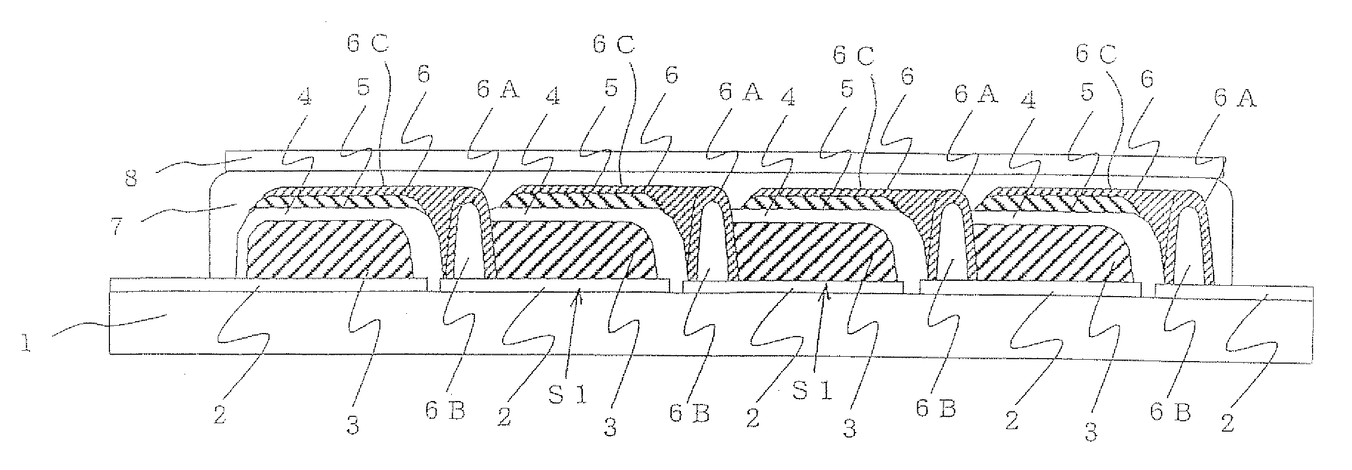
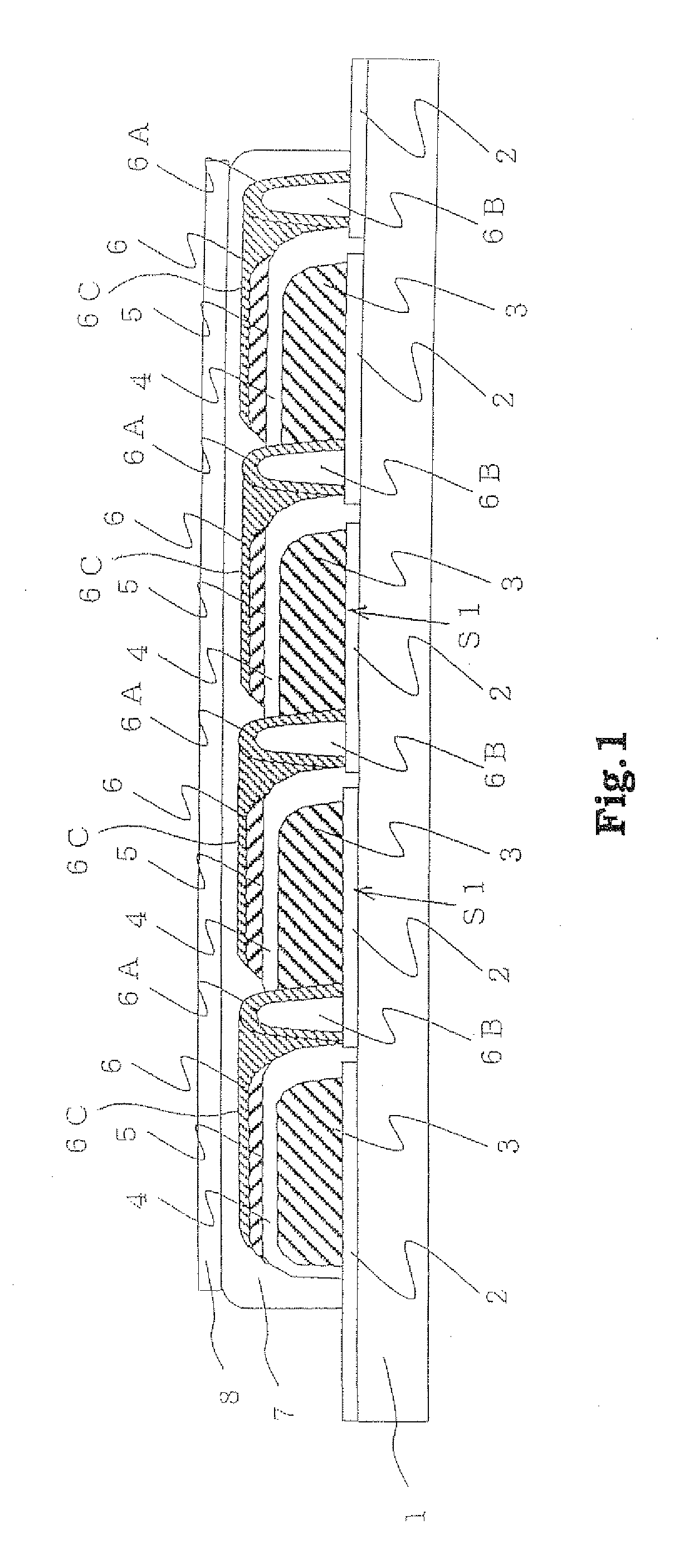
[0119]FIG. 1 is a schematic sectional view showing a constitution of Embodiment 1 of the dye-sensitized solar cell module of the present invention.

[0120]The dye-sensitized solar cell module of Embodiment 1 is composed of a plurality of electrically series-connected solar cells S1 having a transparent insulating substrate 1, a transparent first conductive layer 2 formed on the insulating substrate 1, a photoelectric conversion device obtained by forming a photoelectric conversion layer 3 comprising a porous semiconductor layer adsorbing a dye, a carrier transporting layer 4 and a catalyst layer 5 subsequently on the first conductive layer 2, and a second conductive layer 6 formed on the photoelectric conversion device, wherein all of a plurality of cells S1 are covered with a sealing layer 7 and a cover film 8 is laminated on the sealing layer 7. In addition, existence of transparency of the sealing layer 7 and the cover film 8 is not particularly restricted.

[0121]Structural features...

embodiment 2

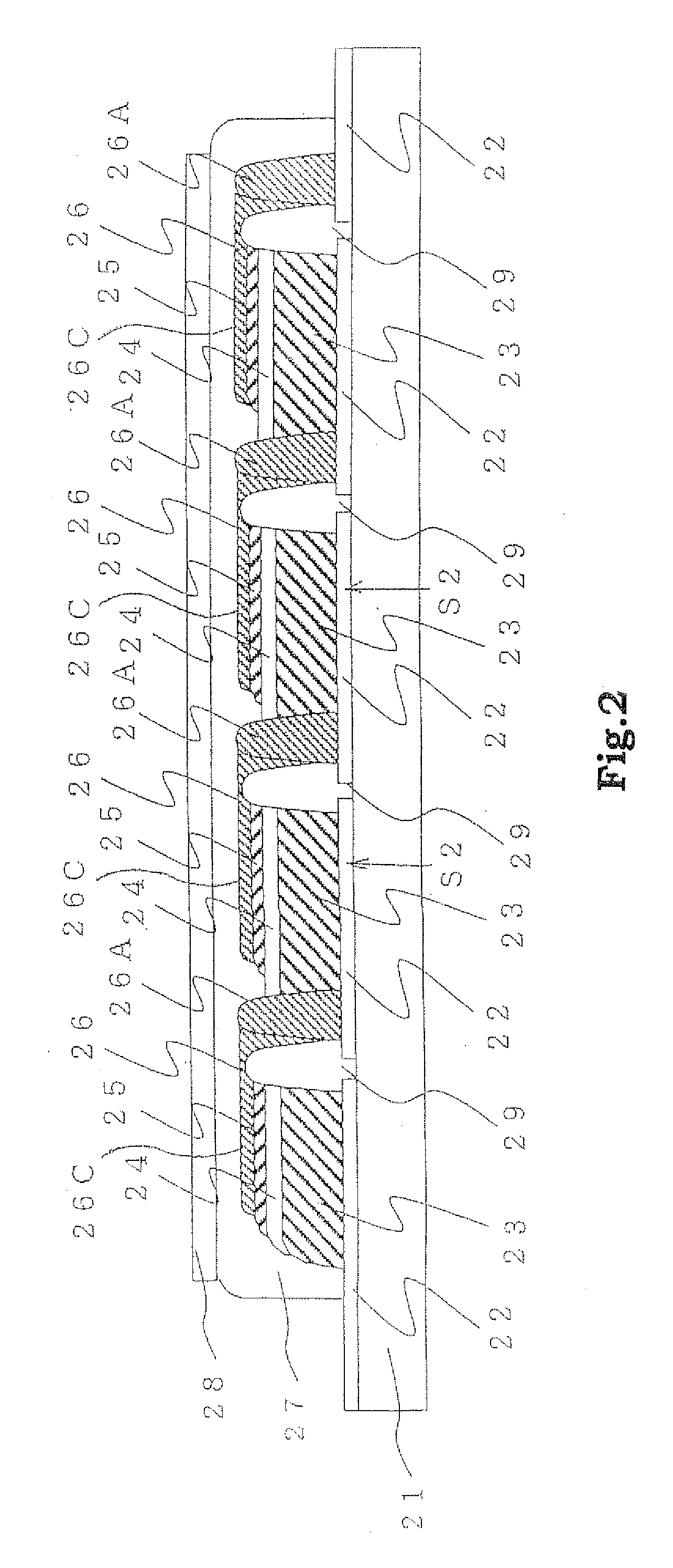
[0126]FIG. 2 is a schematic sectional view showing a constitution of Embodiment 2 of the dye-sensitized solar cell module of the present invention.

[0127]In the same manner as in Embodiment 1, the dye-sensitized solar cell module of Embodiment 2 is composed of a plurality of series-connected solar cells S2 having a transparent insulating substrate 21, a transparent first conductive layer 22 formed on the insulating substrate 21, a photoelectric conversion device obtained by forming a photoelectric conversion layer 23 comprising a porous semiconductor layer adsorbing a dye, a carrier transporting layer 24 and a catalyst layer 25 subsequently on the first conductive layer 22, and a second conductive layer 26 formed on the photoelectric conversion device, wherein all of a plurality of cells S2 are covered with a sealing layer 27 and a cover film 28 is laminated on the sealing layer 27.

[0128]Structural features of this solar cell module of Embodiment 2, differing from those of Embodiment...

embodiment 3

[0132]FIG. 3 is a schematic sectional view showing a constitution of Embodiment 3 of the dye-sensitized solar cell module of the present invention.

[0133]In the same manner as in Embodiments 1 and 2, the dye-sensitized solar cell module of Embodiment 3 is composed of a plurality of series-connected solar cells S3 having a transparent insulating substrate 31, a transparent first conductive layer 32 formed on the insulating substrate 31, a photoelectric conversion device obtained by forming a photoelectric conversion layer 33 comprising a porous semiconductor layer adsorbing a dye, a carrier transporting layer 34 and a catalyst layer 35 subsequently on the first conductive layer 32, and a second conductive layer 36 formed on the photoelectric conversion device, wherein all of a plurality of cells S3 are covered with a sealing layer 37 and a cover film 38 is laminated on the sealing layer 37.

[0134]Structural features of this solar cell module of Embodiment 3, differing from those of Emb...


PUM

PropertyMeasurementUnit
thicknessaaaaaaaaaa
temperatureaaaaaaaaaa
thicknessaaaaaaaaaa

Abstract

A dye-sensitized solar cell module comprising: a plurality of electrically series-connected solar cells having a first conductive layer formed on an insulating substrate; a photoelectric conversion device formed on the first conductive layer; and a second conductive layer formed on the photoelectric conversion device, wherein the photoelectric conversion device has a photoelectric conversion layer having a porous semiconductor layer adsorbing a dye, a carrier transporting layer and a catalyst layer and the dye-sensitized solar cell module is characterized in that the second conductive layer of the above-described one solar cell contacts the first conductive layer of an adjacent another solar cell and the photoelectric conversion device of the above-described adjacent another solar cell contacts the second conductive layer of the above-described one solar cell.

Description

TECHNICAL FIELD[0001]The present invention relates to a dye-sensitized solar cell module and a method of producing the same.BACKGROUND ART[0002]As an alternative energy source to fossil fuel, solar cells capable of converting sun light to electric power have drawn attention. At present, some of solar cells using crystalline silicon substrates and thin film silicon solar cells have started to be used practically. However, the former has a problem of a high production cost of the silicon substrates and the latter has a problem that the production cost is increased since various kinds of gases for semiconductor production and complicated production facilities are required. Therefore, in both solar cells, it has been tried to lower the cost per electric power output by increasing the efficiency of photoelectric conversion; however, the above-mentioned problems still remain while being unsolved.[0003]As a new type solar cell, there has been proposed a wet type solar cell based on photo-i...

Claims


Application Information

Patent Timeline
Patent Type & Authority Applications(United States)
IPC IPC(8): H01L31/042H01L31/18H01L27/142H01M50/528
CPCH01G9/2031H01G9/2059Y02E10/542H01G9/2081Y02P70/50
Inventor YAMANAKA, RYOHSUKEFUKE, NOBUHIROFUKUI, ATSUSHI
Owner SHARP KK
Why Eureka
Try Eureka