Display device and manufacturing method of the same

Active Publication Date: 2010-03-25
SEMICON ENERGY LAB CO LTD
View PDF99 Cites 69 Cited by
  • Summary
  • Abstract
  • Description
  • Claims
  • Application Information

AI Technical Summary

Benefits of technology

[0032]According to an embodiment of the present invention, by stacking the oxide semiconductor layer and the conductive layer in the common connection portion provided in the outer region of the pixel portion, a defect due to the separation

Problems solved by technology

Despite the fact that an oxide semiconductor film can be formed at a low temperature, the product can be defective if a thin film of a metal or the like used for a wiring or an electrode, or an insulating film such as an interlayer insulating film, is sep

Method used


Image

  • Display device and manufacturing method of the same
  • Display device and manufacturing method of the same
  • Display device and manufacturing method of the same

Examples


embodiment 1

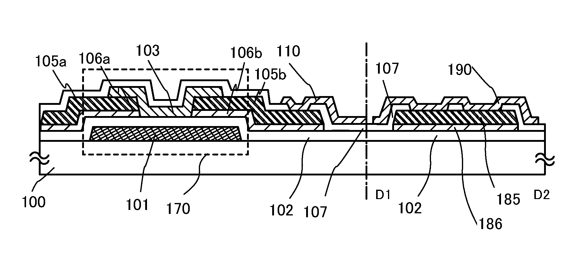
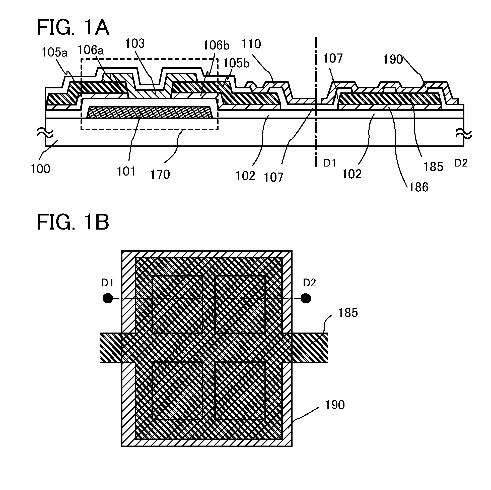
[0068]This embodiment shows an example of a liquid crystal display device in which a liquid crystal layer is sealed between a first substrate and a second substrate, and a common connection portion is formed on the first substrate to be electrically connected to a counter electrode provided on the second substrate. Note that a thin film transistor is formed as a switching element on the first substrate, and the common connection portion is formed through the same manufacturing process as the switching element in a pixel portion so that the process is not complicated.

[0069]The common connection portion is provided in a position overlapping with a sealant for bonding the first substrate and the second substrate and is electrically connected to a counter electrode through conductive particles in the sealant. Alternatively, the common connection portion is provided in a position which does not overlap with the sealant (except for the pixel portion) and a paste including conductive parti...

embodiment 2

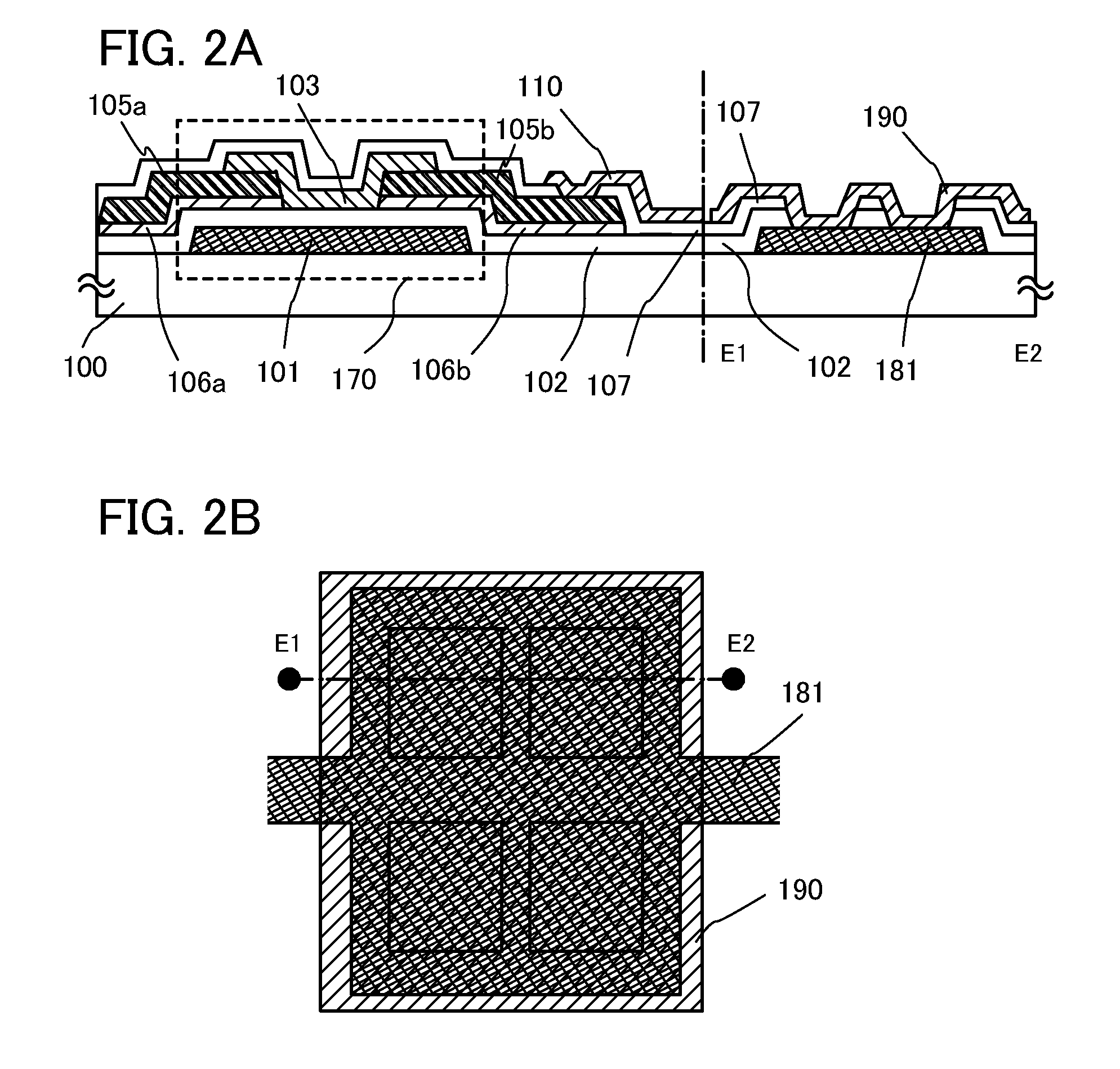
[0084]In this embodiment, an example of manufacturing a common connection portion, in which a wiring formed using the same material and through the same process as a gate wiring is used as a common potential line, will be illustrated in FIGS. 2A and 2B.

[0085]FIG. 2B illustrates an example of a top view of the common connection portion. Dashed line E1-E2 in FIG. 2B corresponds to a cross section of the common connection portion of FIG. 2A.

[0086]Note that as illustrated in FIG. 2A, a thin film transistor in a pixel portion has the same structure as that of Embodiment 1; thus, portions similar to those in FIG. 1A are denoted by the same reference numerals and detailed description is omitted here.

[0087]A common potential line 181 is provided over a substrate 100 and formed using the same material and through the same process as the gate electrode 101.

[0088]In addition, the common potential line 181 is covered with the gate insulating layer 102 and the protective insulating film 107. The...

embodiment 3

[0096]In this embodiment, an example of manufacturing a common connection portion, in which an electrode formed using the same material and through the same process as a gate wiring is formed and a wiring formed using the same material and through the same process as a source electrode layer is provided as a common potential line over the electrode, will be illustrated in FIGS. 3A and 3B.

[0097]FIG. 3B illustrates an example of a top view of the common connection portion. Dashed line F1-F2 in FIG. 3B corresponds to a cross section of the common connection portion of FIG. 3A.

[0098]Note that as illustrated in FIG. 3A, a thin film transistor in a pixel portion has the same structure as that of Embodiment 1; thus, portions similar to those in FIG. 1A are denoted by the same reference numerals and detailed description is omitted here.

[0099]A connection electrode 191 is provided over the substrate 100 and formed using the same material and through the same process as the gate electrode 101...


PUM


Abstract

To provide a structure suitable for a common connection portion provided in a display panel. A common connection portion provided in an outer region of a pixel portion has a stacked structure of an insulating layer formed using the same layer as a gate insulating layer, an oxide semiconductor layer formed using the same layer as a second oxide semiconductor layer, and a conductive layer (also referred to as a common potential line) formed using the same layer as the conductive layer, in which the conductive layer (also referred to as the common potential line) is connected to a common electrode through an opening in an interlayer insulating layer provided over the first oxide semiconductor layer and an electrode opposite to a pixel electrode is electrically connected to the common electrode through conductive particles.

Description

TECHNICAL FIELD[0001]The present invention relates to a display device using an oxide semiconductor and a manufacturing method of the same.BACKGROUND ART[0002]As typically seen in a liquid crystal display device, a thin film transistor formed on a flat plate such as a glass substrate is manufactured using amorphous silicon or polycrystalline silicon. Although the field effect mobility of an amorphous silicon thin film transistor is low, it can be formed on a large glass substrate. On the other hand, the field effect mobility of a polycrystalline silicon thin film transistor is high; however, it cannot always be formed on a large glass substrate because of a crystallization process such as laser annealing.[0003]Techniques have attracted attention, where a thin film transistor using an oxide semiconductor is manufactured and applied to electronic devices or optical devices. Examples of the techniques are disclosed in Reference 1 and Reference 2, where a thin film transistor is manufac...

Claims


Application Information

Patent Timeline
IPC IPC(8): H01L29/786H01L33/00
CPCH01L27/1225H01L29/7869H01L27/124H01L2924/0002H01L2924/00G02F1/1368G09F9/30H01L27/1214
Inventor YAMAZAKI, SHUNPEIAKIMOTO, KENGOKOMORI, SHIGEKIUOCHI, HIDEKIWADA, RIHITOCHIBA, YOKO
Owner SEMICON ENERGY LAB CO LTD
Why Eureka
Try Eureka