
System and Method for Multilane Link Rate Negotiation

a multi-lane link and rate technology, applied in the field of communication systems, to achieve the effect of high throughput, low network throughput requirement, and more power conservatism

Active Publication Date: 2010-03-25
MACOM CONNECTIVITY SOLUTIONS LLC
View PDF6 Cites 19 Cited by
  • Summary
  • Abstract
  • Description
  • Claims
  • Application Information

AI Technical Summary

Benefits of technology

[0009]Disclosed herein are a system and method that permits physical layer devices (PHY) to negotiate rates over copper cable or optical links. With a compliant link partner, a rate can be selected at one end to match throughput requirements. The 1 G is more power conservative, and is useful when network throughput requirement are low. However, the 10 G is desirable when high throughput is required. The disclosed system automatically links partners with different link preferences, even if the link partners do not have an AN capability. Optionally, training for 10 G links may be supported to optimize performance, especially with highly dispersive, high loss cables.

Problems solved by technology

However, if one of the devices cannot send AN messages, the other device times-out, and a link data rate is established at the data rate transmitted by the device that is not AN-capable.

Method used


Image

  • System and Method for Multilane Link Rate Negotiation
  • System and Method for Multilane Link Rate Negotiation
  • System and Method for Multilane Link Rate Negotiation

Examples


Embodiment Construction

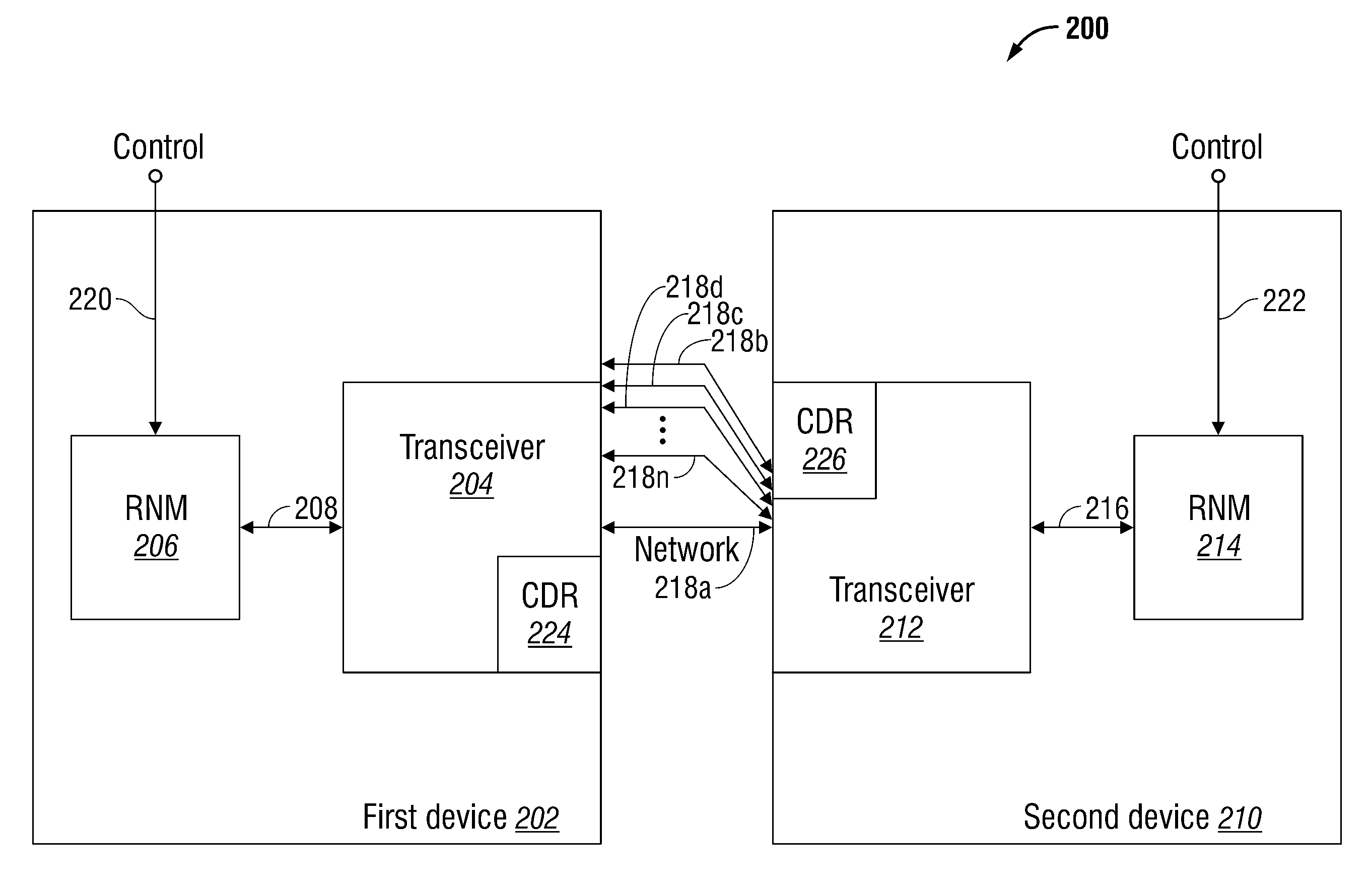
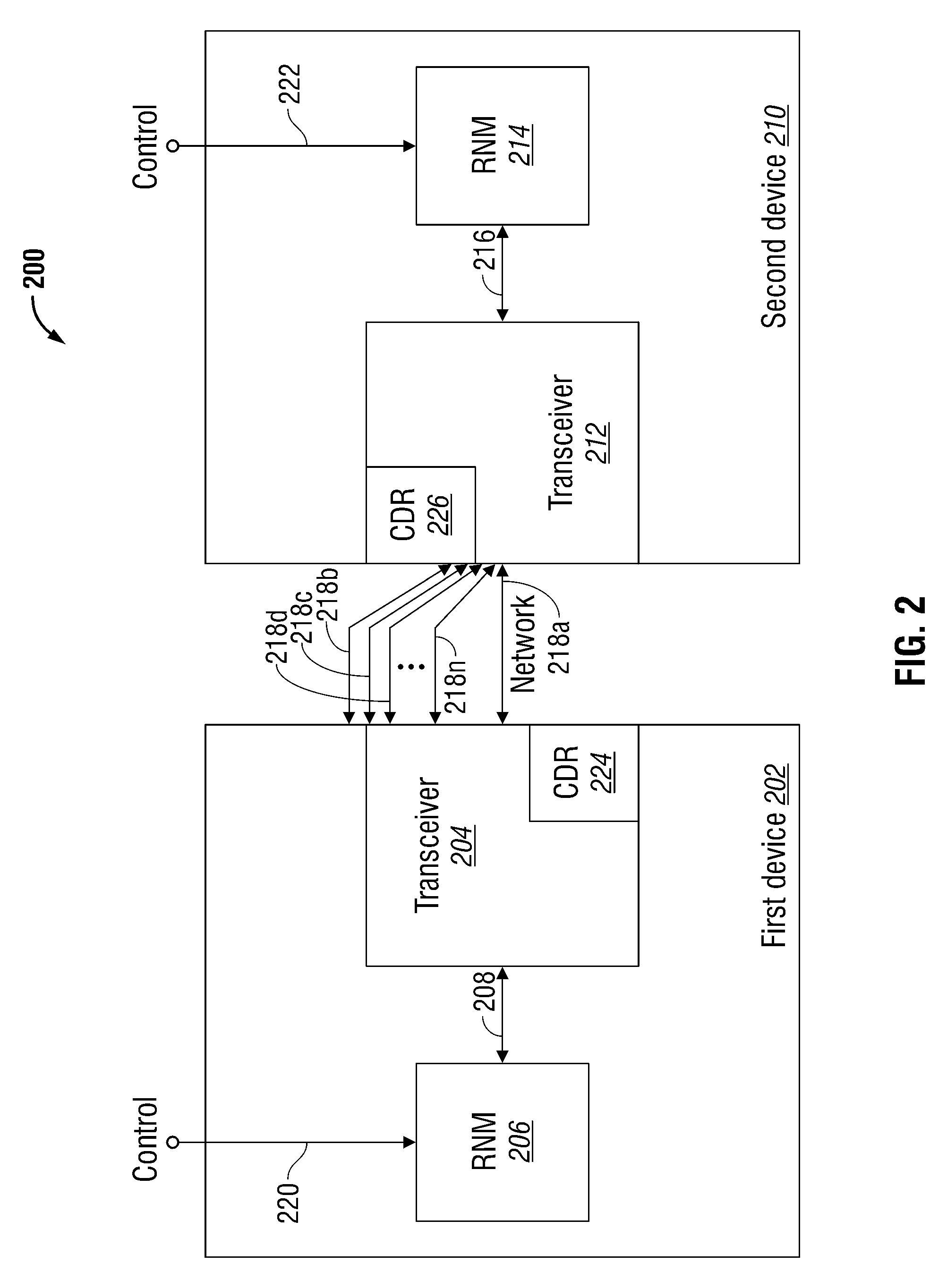
[0023]FIG. 2 is a schematic block diagram of a system for negotiating a link data rate in a communication network using a plurality of data rates. The system 200 comprises a first device 202 with a transceiver 204 interfaced to a rate negotiation module 206 on line 208. A second device 210 has a transceiver 212, interfaced to a rate negotiation module 214 on line 216, and is network-connected to the first device transceiver on line 218. The rate negotiation module (RNM) 206 of the first device 202 and the RNM 214 of rate second device 210 mutually order the transmission of predetermined inquiry signals in the event that a negotiated data rate has not been determined.

[0024]In one scenario, the first device 202 transmits the inquiry signal at a first data rate and the second device transmits the inquiry signal at a second data rate. The first and second data rates may be data rates associated with a single physical medium lane 218a, or a plurality of physical medium lanes, 218b throug...


PUM


Abstract

A system and method are provided for negotiating a link data rate in a communication system using a plurality of data rates. In a system including a first device network-connected to a second device, auto-negotiation (AN) messages are mutually transmitted. The AN messages indicate rate information such as preferred data rate capabilities, if the device has a dual-rate capability, single data rate capabilities, or is capable of communicating over a plurality of physical medium lanes. If the AN messages are mutually transmitted, a negotiated link data rate is established. However, if one of the devices cannot send AN messages, the other device times-out, and a link data rate is established at the data rate transmitted by the device that is not AN-capable.

Description

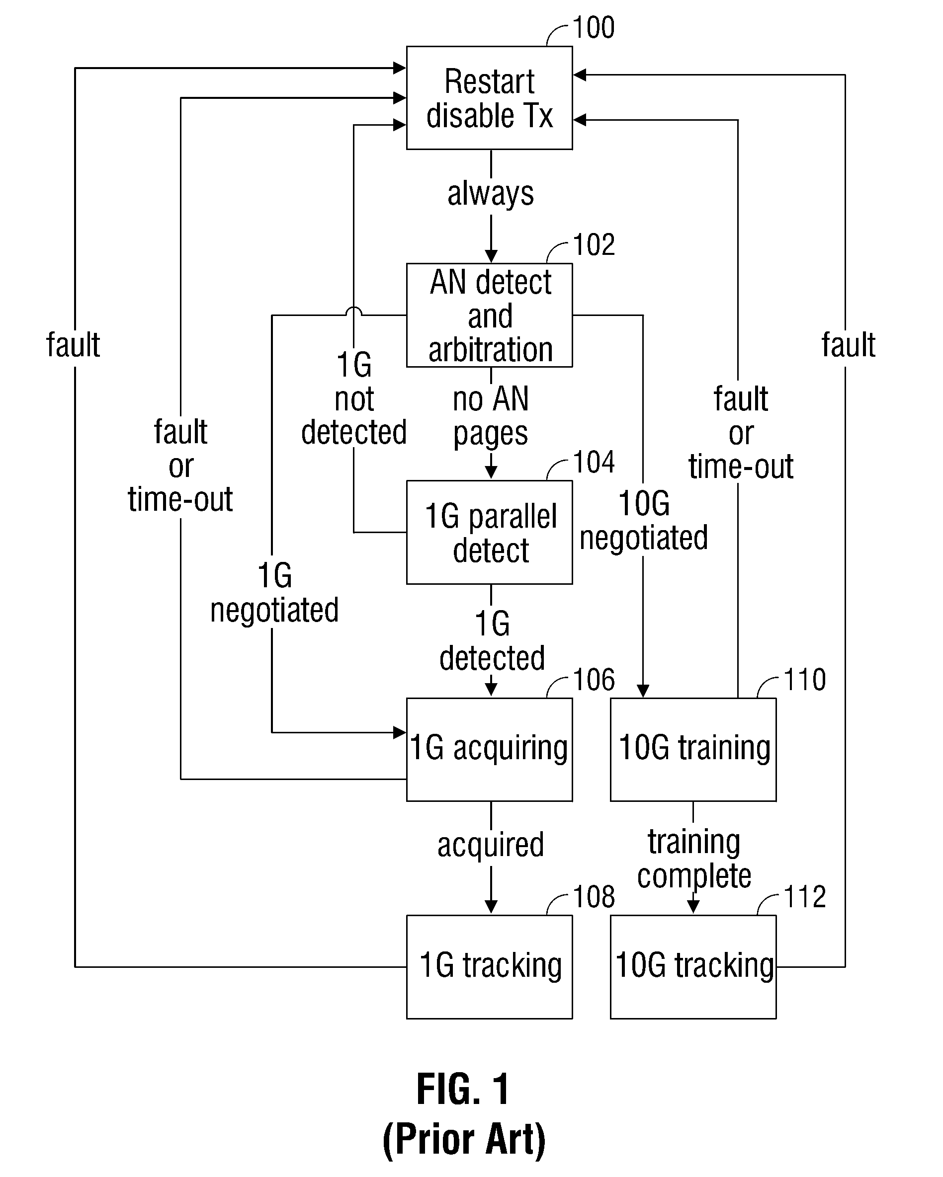
RELATED APPLICATIONS[0001]This application is a continuation-in-part of a pending application entitled, SYSTEM AND METHOD FOR LINK RATE NEGOTIATION, invented by Brown et al., Ser. No. 12 / 236,918, filed Sep. 24, 2008, 2008, attorney docket no. applied—285, which is incorporated herein by reference.BACKGROUND OF THE INVENTION[0002]1. Field of the Invention[0003]This invention generally relates to communication systems and, more particularly, to a system and method for negotiating a link rate in a communication system where link partners are optionally capable of transceiving at two or more data rates, on one or more physical medium lanes.[0004]2. Description of the Related Art[0005]FIG. 1 is an auto-negotiation and training state diagram for an IEEE 802.3ap compliant network (prior art). The diagram is a state machine demonstrating the steps in an auto-negotiation (AN) process between boards across a backplane. Devices in such a backplane may be capable of operating at 1 gigabits per ...

Claims


Application Information

Patent Timeline
IPC IPC(8): G06F15/16
CPCH04L29/04H04L47/10Y02B60/33H04L69/24H04L69/14Y02D30/50
Inventor BROWN, MATTHEWHEROD, MARIKAGAO, YANMING
Owner MACOM CONNECTIVITY SOLUTIONS LLC
Learn More