

Battery temperature control system
a temperature control system and battery technology, applied in battery overheating protection, safety/protection circuits, transportation and packaging, etc., can solve the problems of delayed battery temperature rise, battery voltage between both ends, and battery charging/discharging power may go out of an appropriate range, so as to reduce vibration noise and/or driving force fluctuation
- Summary
- Abstract
- Description
- Claims
- Application Information
AI Technical Summary
Benefits of technology
Problems solved by technology
Method used
Image

Examples
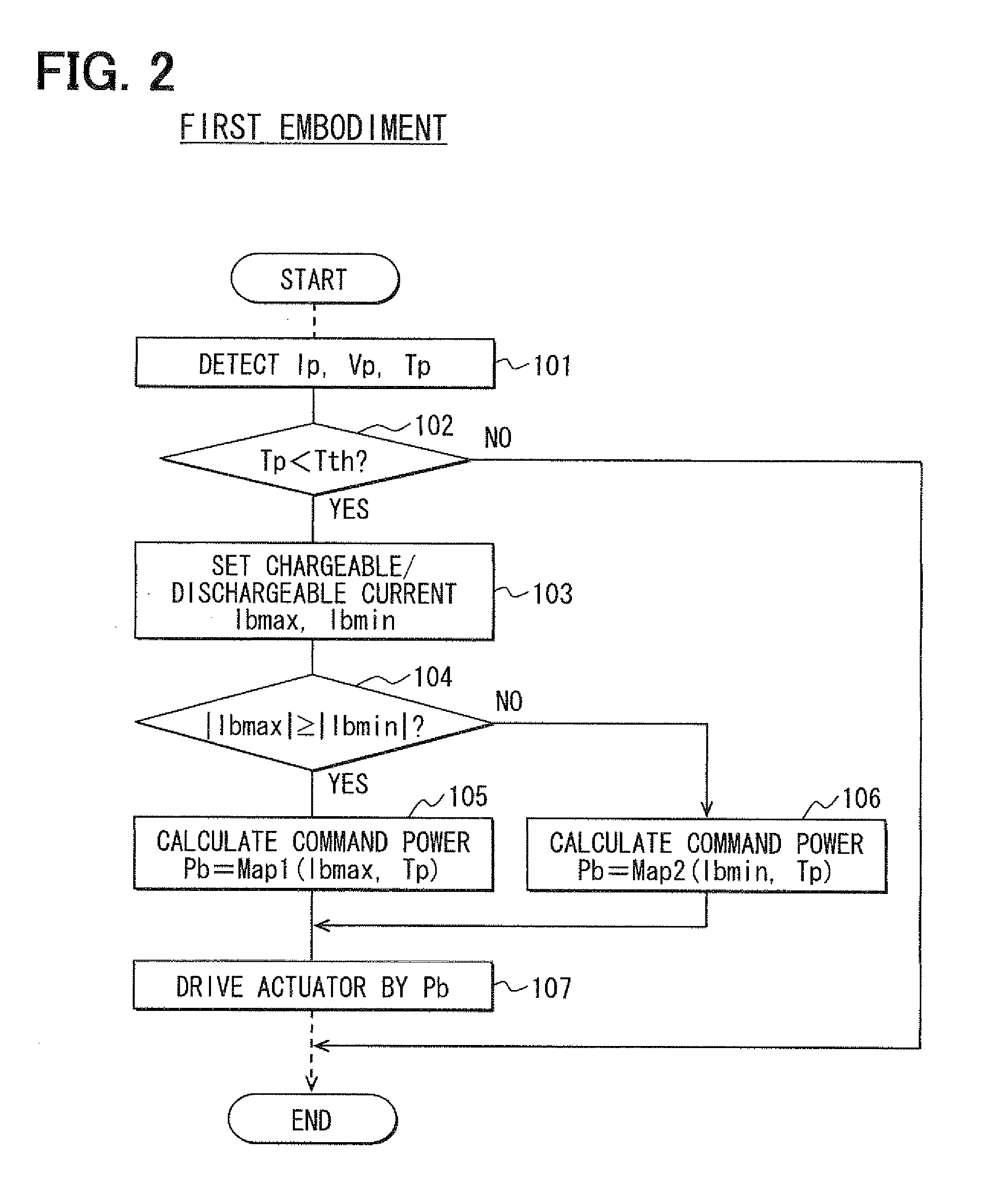
first embodiment
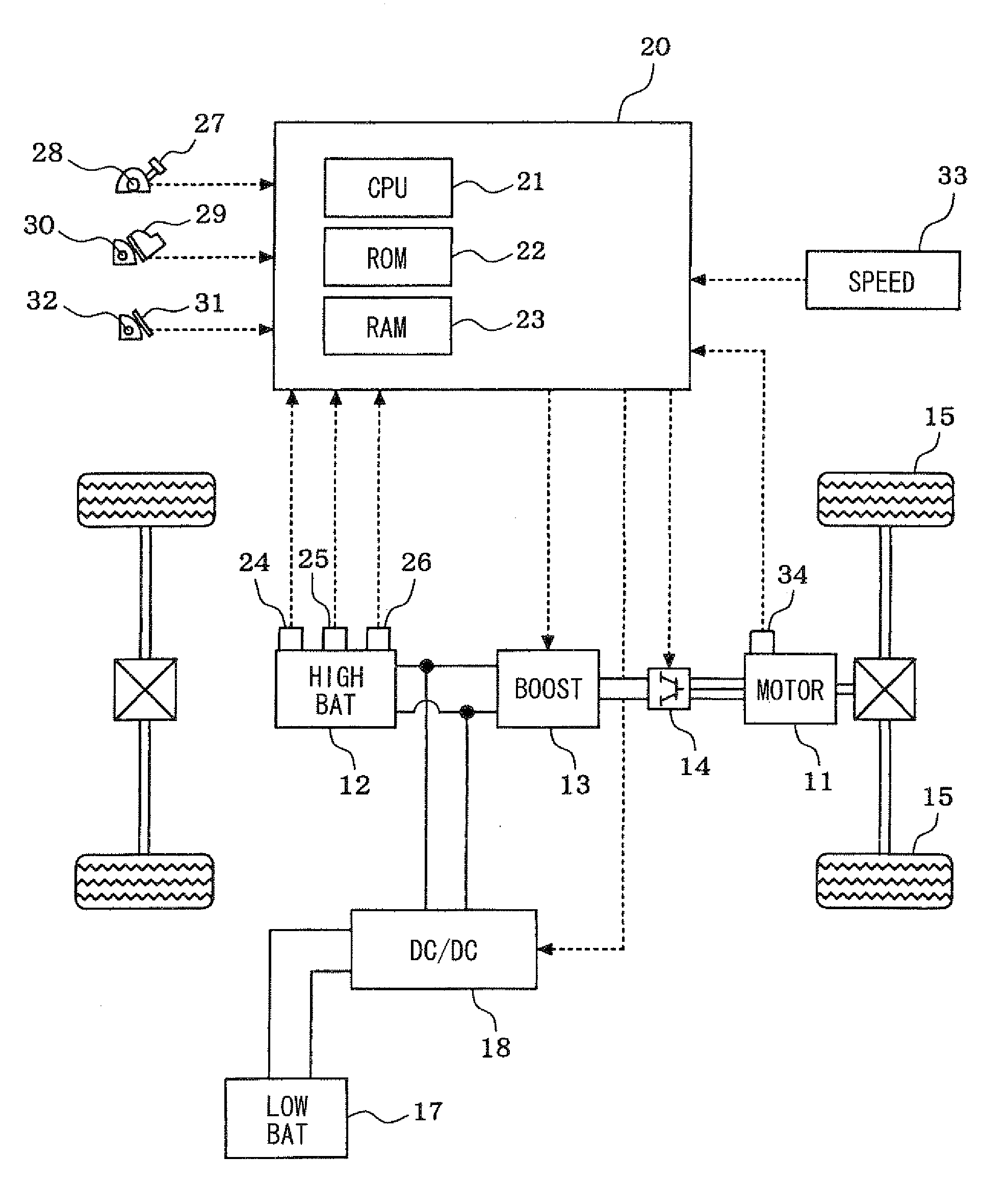
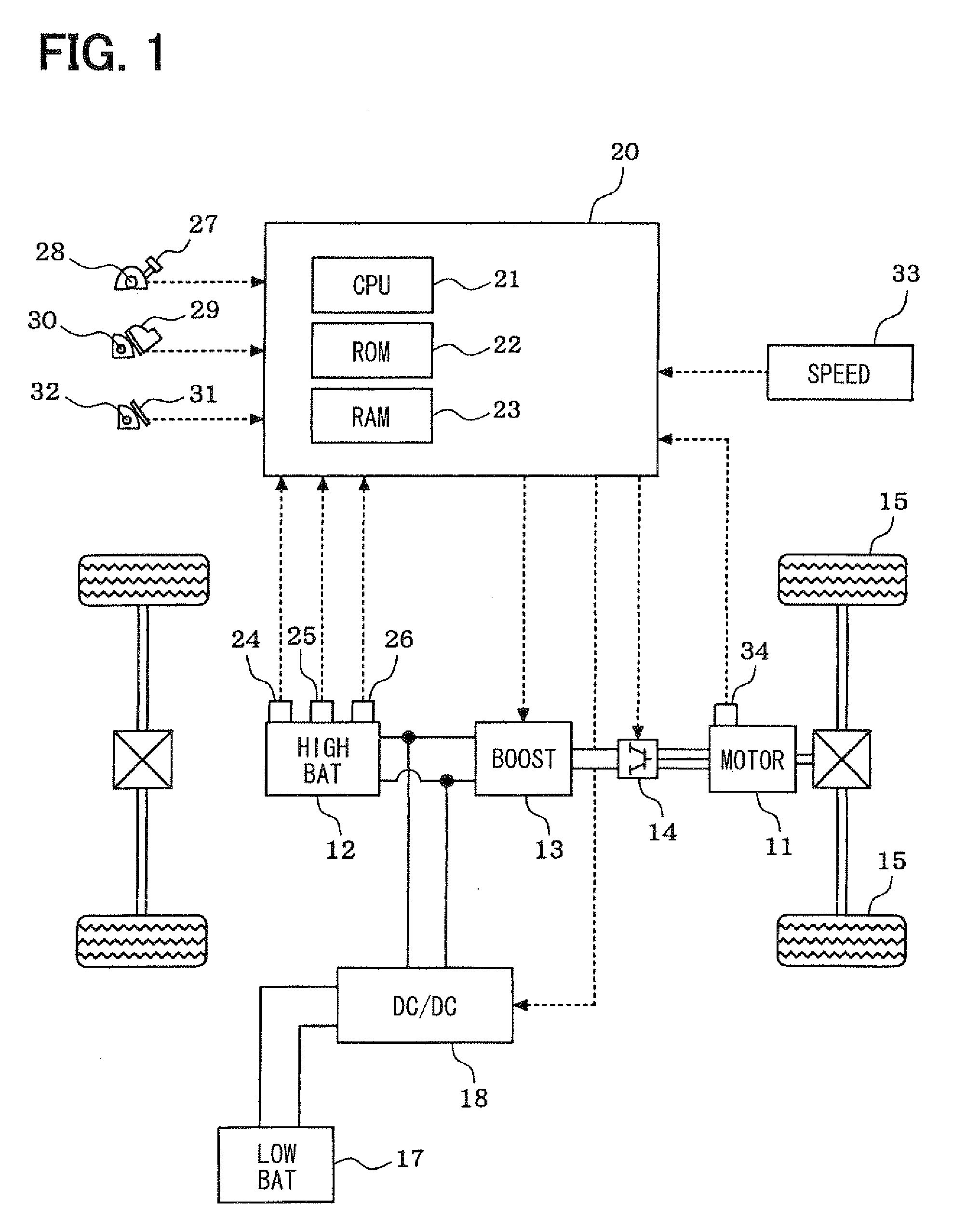
[0043]As illustrated in FIG. 1, an electric vehicle is mounted with: a motor 11 as a vehicle driving source; a high-voltage battery 12 as a power source for this motor 11; and a low-voltage battery 17 as a power source for various pieces of electrical equipment (electrical loads). The motor 11 comprised of a synchronous generator motor as a motor also used as a generator. The high-voltage battery 12 is comprised of a secondary battery, such as a lithium (Li)-ion battery and a nickel-hydrogen battery, that outputs high voltage of, for example, 200 to 300V.
[0044]Between the motor 11 and the high-voltage battery 12, a boost converter 13 and an inverter 14 are provided. When the motor 11 is driven, a DC voltage outputted from the high-voltage battery 12 is stepped up at the boost converter 13 and converted into an AC voltage at the inverter 14 and then supplied to the motor 11. As a result, the motor 11 is rotated and the driving wheels 15 of the vehicle are driven. When the motor 11 ge...
second embodiment
[0062]In the first embodiment, the maximum chargeable current Ibmin and the maximum dischargeable current Ibmax in the temperature rise control are set by a map, a mathematical expression, or the like based on the current, voltage, and temperature of the high-voltage battery 12. As indicated in FIG. 3, however, the internal resistance of the high-voltage battery 12 is increased under cold condition. Therefore, it is preferable that the maximum chargeable current Ibmin and the maximum dischargeable current Ibmax in the temperature rise control should be determined based on use limitation on voltage in the high-voltage battery 12.
[0063]In the second embodiment illustrated in FIG. 4 and FIG. 5, consequently, to accurately set the maximum chargeable current Ibmin and the maximum dischargeable current Ibmax, the difference between the upper and lower limit values within the voltage use range (allowable range) of the high-voltage battery 12 illustrated in FIG. 5 and the sampled present vo...
third embodiment
[0076]In the second embodiment, to take into account the influence of the internal resistance of the high-voltage battery 12, the detected temperature Tp of the high-voltage battery 12 is used to set the maximum chargeable current Ibmin and the maximum dischargeable current Ibmax. In the third embodiment illustrated in FIG. 6 and FIG. 7, attention is directed to the relation that under cold condition, the internal resistance of the high-voltage battery 12 is increased with reduction in its temperature. Then the internal resistance Rb is estimated based on the detected temperature Tp of the high-voltage battery 12 and the estimated internal resistance Rb is used to set the maximum chargeable current Ibmin and the maximum dischargeable current Ibmax.
[0077]In the temperature rise control routine in the third embodiment illustrated in FIG. 6, the processing of step 205 in the temperature rise control routine in FIG. 4 is replaced with the processing of steps 205a and 205b. The processin...
PUM
 Abstract
Description
Claims
Application Information