
Method for preparing abrasive waterjet mixing tubes

Inactive Publication Date: 2010-04-15
KENNAMETAL INC
View PDF20 Cites 6 Cited by
  • Summary
  • Abstract
  • Description
  • Claims
  • Application Information

AI Technical Summary

Benefits of technology

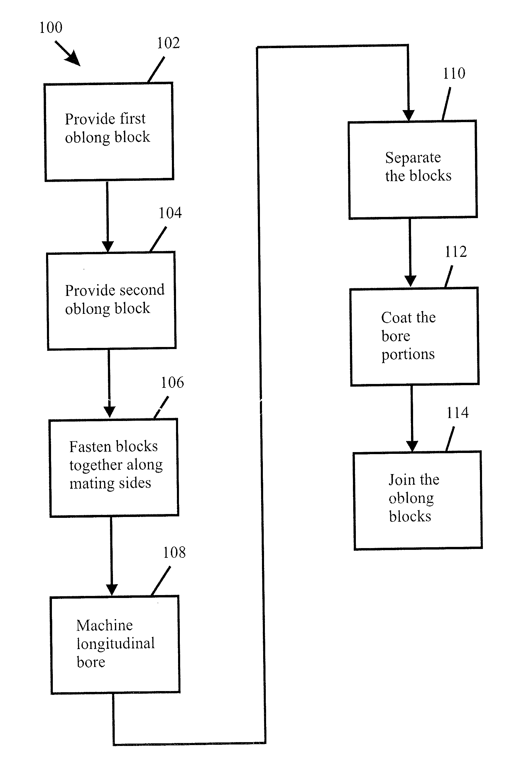
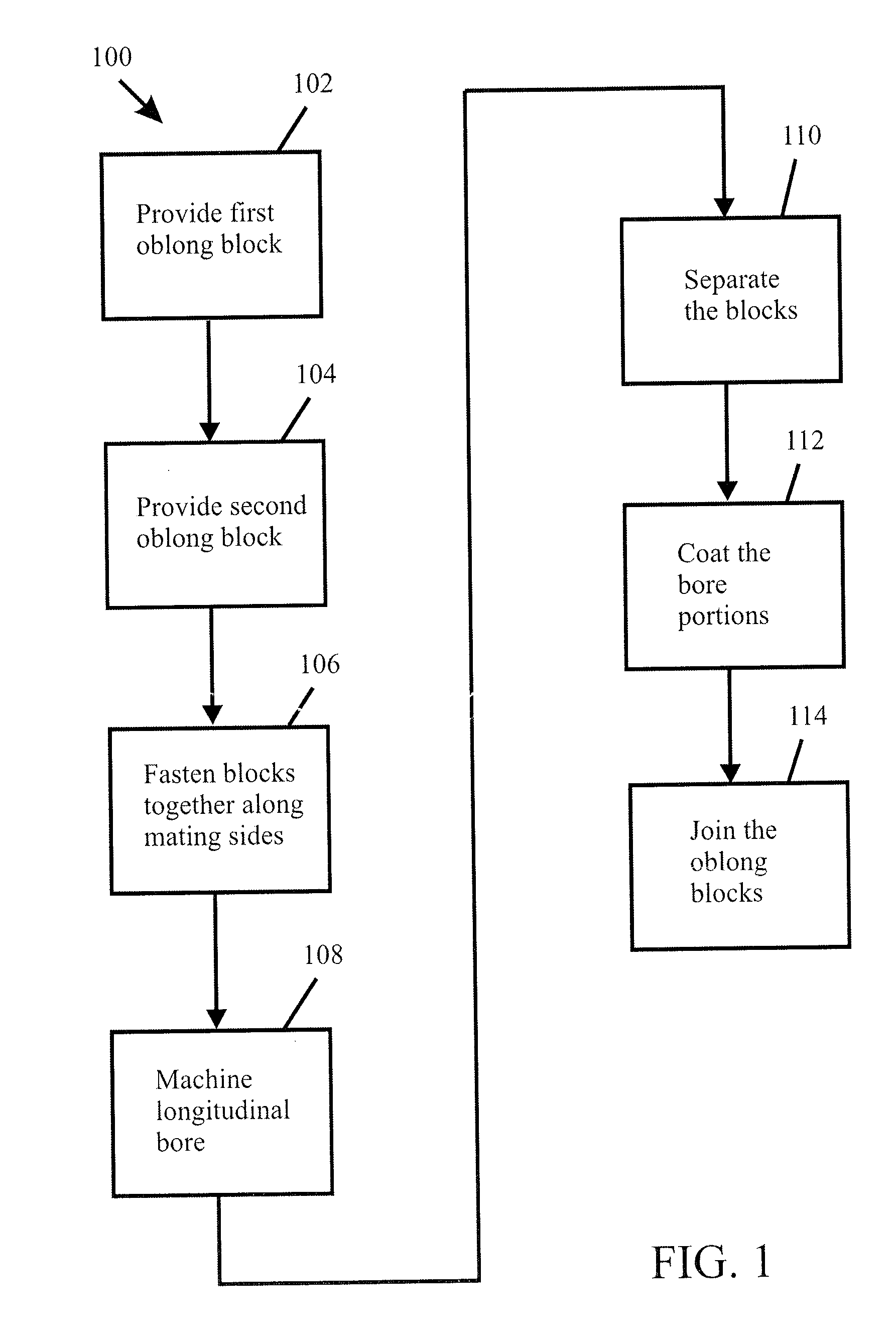
[0009]The present invention provides methods of manufacturing AWJ mixing tubes having abrasion-resistant material coated longitudinal bores while overcoming at least some of the aforementioned drawbacks of the prior art. In accordance with the present invention, methods are provided for making AWJ mixing tubes using two blocks, each block having a mating surface parallel to its longitudinal axis. These two blocks are fastened together along their respective mating surfaces. A longitudinal bore is then machined across a portion of the longitudinal junction formed by the two mating surfaces. This simultaneous machining of the complimentary parts of the longitudinal bore in each of the two mating surfaces obviates the misalignment problems inherent in the prior art groove-coat-join methods while eliminating the costs associated with requirements for high precision and repeatability of those prior art methods. After the longitudinal bore is machined, the two blocks are separated and an abrasion-resistant coating is applied to the complimentary portions of the longitudinal bore. The two blocks are then joined together to form at least an abrasion-resistant material coated part of an AWJ mixing tube longitudinal bore.

Problems solved by technology

However, the precision and the efficiency of AWJ machining is greatly affected by wear of the longitudinal bore of the mixing tube.
Although the longitudinal bore diameters generally are on the order of 0.010 to 0.060 inches (0.25 to 1.5 mm) and the overall lengths of AWJ mixing tubes are usually on the order of 2 to 4 inches (5 to 10 cm), longitudinal bore diameter erosion of just a few thousands of an inch (a few hundredths of a millimeter) can greatly reduce the machining efficiency and degrade the machining precision, especially when the longitudinal bore erosion is near the exit end of the mixing tube.
AWJ mixing tube longitudinal bore wear results in longer machining times, less precise machining, down time for replacing the worn mixing tube, and the cost of the replacement AWJ mixing tubes.
There has been much effort in the art to harden the AWJ mixing tube against abrasive wear by depositing a hard coating on the surface of its longitudinal bore.
However, because of the high length-to-diameter ratios of the longitudinal bores and the line-of-sight deposition path limitation of the various vapor deposition methods, e.g., chemical vapor deposition (“CVD”) and physical vapor deposition (“PVD”) and their variants, it has not been possible to directly coat the interior of the longitudinal bore with much success.
These approaches, however, are very complex, require handling of the brittle deposited films, and involve difficult matching of a brittle core to an outer support member to achieve a favorable tensile stress state at the working surface of the longitudinal bore.
Mismatched alignment of the longitudinal bore halves results in a misshaped AWJ cutting stream and can cause accelerated wear of the AWJ mixing tube.
Furthermore, the high level of precision and repeatability adds cost to the manufacturing process.

Method used


Image

  • Method for preparing abrasive waterjet mixing tubes
  • Method for preparing abrasive waterjet mixing tubes

Examples


Embodiment Construction

[0012]In this section, some preferred embodiments of the present invention are described in detail sufficient for one skilled in the art to practice the present invention. It is to be understood, however, that the fact that a limited number of preferred embodiments are described herein does not in any way limit the scope of the present invention as set forth in the appended claims.

[0013]Referring to FIG. 1, there is shown a flow diagram for a method 100 of making an AWJ mixing block according to a preferred embodiment of the present invention. The method 100 comprises steps 102-114. In steps 102, 104, two blocks of a suitable material are provided. Each of the blocks has a mating surface running parallel to its longitudinal axis. Preferably, each of the blocks has a semi-cylindrical or semi-conical shape, and more preferably each of the blocks has a shape corresponding to one half of the AWJ mixing tube that is to be made. However, the blocks may have other shapes and further machin...


PUM

PropertyMeasurementUnit
Percent by massaaaaaaaaaa
Lengthaaaaaaaaaa
Timeaaaaaaaaaa

Abstract

A method for making an AWJ mixing tube having a longitudinal bore coated with an abrasion-resistant material, such as diamond. Two blocks having mating longitudinal sides are fastened together prior to machining the longitudinal bore along the junction of their mating surfaces. The blocks are separated and the complementary portions of the longitudinal bore are coated with an abrasion-resistant material. The two blocks are then joined together with the complementary portions of the longitudinal bore aligned to form the longitudinal bore.

Description

FIELD OF THE INVENTION[0001]The present invention relates to methods of preparing abrasive waterjet mixing tubes having bores coated with an abrasion resistant material.BACKGROUND OF THE INVENTION[0002]Abrasive water jet (“AWJ”) machining utilizes a very narrow stream of high pressure water laden with abrasive particles to erosion cut through a workpiece. The AWJ process AWJ machining is used in nearly every industry, including the automobile, aerospace, computer, electronic, and glass industries, to create precision parts from a wide variety of materials such as plastics, metals, glass, composites, ceramics, and rock, including those materials which are otherwise difficult to machine or cut. The AWJ process machines with high precision, very little kerf, and produces a clean, smooth edge thereby reducing or eliminating the need for costly post-machining edge treatment operations. Because AWJ machining is a low temperature operation, it produces no heat affected zone in the machined...

Claims


Application Information

Patent Timeline
IPC IPC(8): B24C5/04B21D51/00B23P11/00
CPCB24C1/045B24C5/04Y10T29/49893Y10T29/49432Y10T29/49885Y10T29/49433
Inventor STARK, ROGER M.GARDNER, JEFFREY G.O'MALLEY, MICHAEL J.
Owner KENNAMETAL INC
Learn More