Plasma processing apparatus and plasma processing method

a processing apparatus and plasma technology, applied in the field of plasma processing apparatus, can solve the problems of insufficient consideration of effective suppression of etching or insufficient consideration of improving the processing rate, and the high-power si etching process as shown above would involve very considerable etching or wear of the dielectric plate made of quartz, so as to improve the processing rate, and reduce the effect of etching or wear

Active Publication Date: 2010-04-15
PANASONIC CORP
View PDF8 Cites 323 Cited by
  • Summary
  • Abstract
  • Description
  • Claims
  • Application Information

AI Technical Summary

Benefits of technology

[0027]According to the plasma processing apparatus and plasma processing method of the present invention, the dielectric plate is supported by the beam-shaped structure which includes an annular outer peripheral portion, a central portion located at the center of the region surrounded by the outer peripheral portion, and a plurality of beam portions extending radially from the central portion to the outer peripheral portion, and moreover the apparatus includes a first gas introducing port having a depression angle directed toward the substrate to inject the process gas, as well as a plurality of second gas introducing ports each having an elevation angle directed toward the dielectric plate to inject either one of a rare gas or oxygen gas. Thus, the plasma processing apparatus and plasma processing method are enabled to achieve improvement of processing rates such as etching rate as well as effective suppression of wear of the dielectric plate.
[0028]Also, since a plurality of process gas introducing ports provided in the surface of the beam-shaped structure facing the window portion of its outer peripheral portion include those having at least two kinds of depression angles, the plasma processing apparatus and plasma processing method are enabled to achieve improvement of the processing rate such as etching rate as well as uniformization of the processing characteristics such as etching rate distribution.

Problems solved by technology

However, such high-pressure, high-power Si etching process as shown above would involve very considerable etching or wear of the dielectric plate made of quartz.
In conventionally proposed plasma processing apparatuses including those disclosed in Patent Literatures 1 to 5, not enough considerations are given to effective suppression of etching or wear of the dielectric plate based on the process characteristics of such high-pressure, high-power, process.
However, in conventionally proposed plasma processing apparatuses including those disclosed in Patent Literatures 1 to 5, not enough considerations are given to improvement of the processing rate such as etching rate based on the characteristics of the high-pressure process, as well as to uniformization of processing characteristics such as etching rate distribution.

Method used


Image

  • Plasma processing apparatus and plasma processing method
  • Plasma processing apparatus and plasma processing method
  • Plasma processing apparatus and plasma processing method

Examples


first embodiment

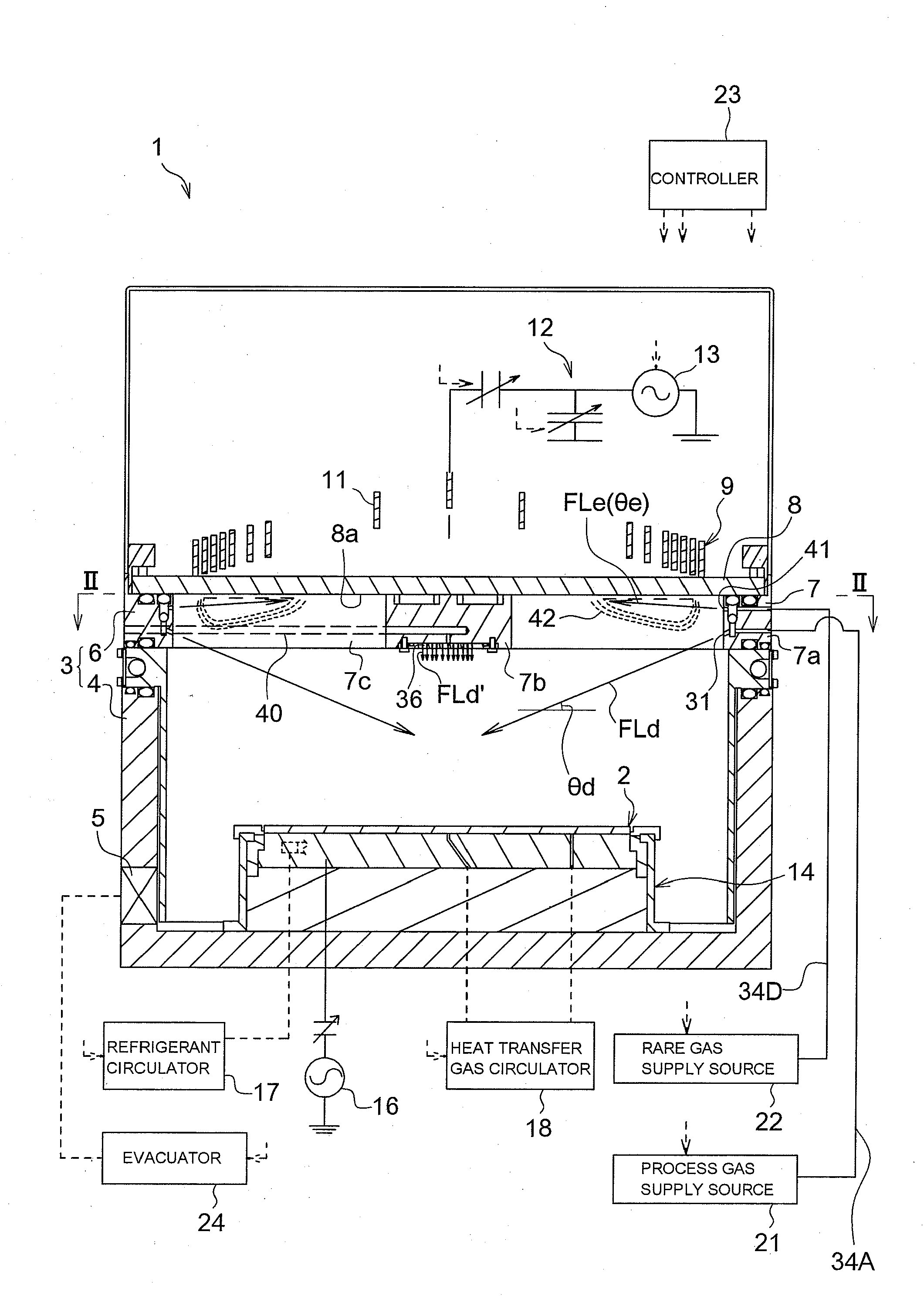
[0082]FIGS. 1 and 2 show a dry etching apparatus 1 of ICP (Inductively Coupled Plasma) type according to an embodiment of the present invention. The dry etching apparatus 1 has a chamber (vacuum vessel) 3 that constitutes a processing chamber in which a substrate 2 is housed. The chamber 3 has a chamber main body 4 whose upper part is opened, and a lid 6 that seals the upper opening of the chamber main body 4. The chamber main body 4 is provided with a gate (not shown) for carrying in and out the substrate 2. The lid 6 has a beam-shaped spacer (beam-shaped structure) 7 supported by the upper end of the side wall of the chamber main body 4, and a disc-shaped dielectric plate 8 that functions as a top plate supported by the beam-shaped spacer 7.

[0083]In this embodiment, the target substrate 2 is made of silicon, and the dry etching apparatus 1 executes about 10 Pa or higher high-pressure (low degree of vacuum), high-power, ultrahigh-density plasma generation process for etching the si...

second embodiment

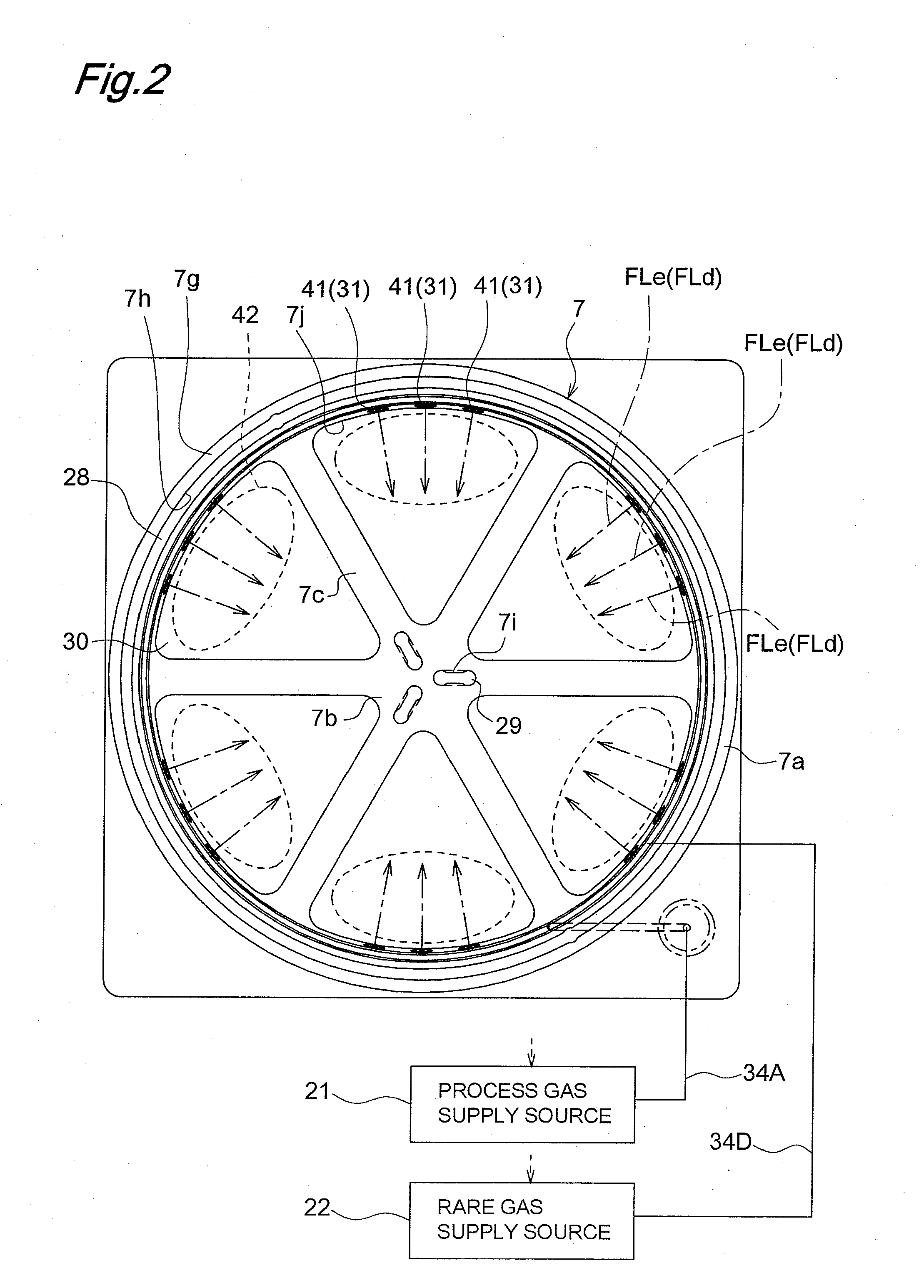
[0127]In a dry etching apparatus 1 of the ICP type according to a second embodiment of the invention shown in FIGS. 10 to 13, the process gas is injected only from process gas introducing ports 31 provided in the outer peripheral portion 7a of the beam-shaped spacer 7, while the rare gas is injected only from rare gas introducing ports 61, 62 provided in the central portion 7b of the beam-shaped spacer 7.

[0128]Referring to FIGS. 10, 11 and 12, the process gas introducing port chips 44 having the process gas introducing ports 31 are mounted at fitting holes 50 communicating with the upper annular gas passage 33B out of the two-stage annular gas passages 33A, 33B of the outer peripheral portion 7a of the beam-shaped spacer 7. Also, the introducing passage 34A on the process gas supply source 21 side is connected to the upper annular gas passage 33B. Accordingly, the process gas is injected from the process gas introducing ports 31 after passing from the process gas supply source 21 th...

third embodiment

[0131]In a dry etching apparatus 1 according to a third embodiment of the invention shown in FIG. 14, the process gas is injected only from the process gas introducing ports 36 provided in the central portion 7b of the beam-shaped spacer, while the rare gas is injected only from the rare gas introducing ports 41 provided in the outer peripheral portion 7a of the beam-shaped spacer 7.

[0132]The rest of construction and function of the third embodiment are similar to those of the first embodiment. Therefore, like component members are designated by like reference signs and their description is omitted.


PUM

PropertyMeasurementUnit
pressureaaaaaaaaaa
thicknessaaaaaaaaaa
diameteraaaaaaaaaa

Abstract

A plasma processing apparatus includes a beam-shaped spacer 7 which is placed at an upper opening of a chamber 3 opposed to a substrate 2 to support a dielectric plate 8. The dielectric plate 8 is supported by the beam-shaped spacer 7. In the beam-shaped spacer 7 are provided a plurality of process gas introducing ports 31, 36 which have a depression angle θd and which are provided downward and directed toward the substrate 2, as well as a plurality of rare gas introducing ports 41 having a elevation angle θe directed toward the dielectric plate 8. Improvement of processing rates such as etching rate as well as effective suppression of wear of the dielectric plate 8 can be achieved.

Description

TECHNICAL FIELD[0001]The present invention relates to a plasma processing apparatus, as well as a plasma processing method, such as dry etching apparatus and plasma CVD apparatus.BACKGROUND ART[0002]In a plasma processing apparatus of the inductively coupled plasma (ICP) type, a construction that an upper portion of the chamber is closed with a dielectric plate, and a coil to which a radio frequency power is applied is placed on the dielectric plate is known. For example, Patent Literatures 1 to 3 disclose plasma processing apparatuses in which the dielectric plate is reduced in thickness while the mechanical strength is secured by supporting the lower surface side of the dielectric plate with a beam-shaped structure. Also, Patent Literatures 4 and 5 disclose constructions for supplying gas from a dielectric-plate supporting structure.[0003]In these plasma processing apparatuses, since the dielectric plate is thin and the beam-shaped structure is so shaped as to reduce interaction w...

Claims


Application Information

Patent Timeline
Patent Type & Authority Applications(United States)
IPC IPC(8): C23F1/00C23C16/00C23F1/08C23C16/505
CPCC23C16/45574C23C16/4558H05H1/46H01J37/321H01J37/3244C23C16/507H01L21/205H01L21/3065
Inventor HIROSHIMA, MITSURUASAKURA, HIROMI
Owner PANASONIC CORP
Why Eureka
Try Eureka