Friction stir welding of dissimilar metals

a technology of friction stir welding and dissimilar metals, which is applied in the direction of welding/soldering/cutting articles, non-electric welding apparatus, manufacturing tools, etc., can solve the problems of not only restricting the size of the stir zone, weakening an intended weld, etc., to reduce the tendency of intermetallic liquid to stick to the weld tool, improve the mechanical properties of the fsw, and increase the viscosity of the intermetallic liquid

Inactive Publication Date: 2010-04-15
GM GLOBAL TECH OPERATIONS LLC
View PDF27 Cites 75 Cited by
  • Summary
  • Abstract
  • Description
  • Claims
  • Application Information

AI Technical Summary

Benefits of technology

[0008]Such powder compositions are chosen by experience or experiment for improving the mechanical properties of the FSW. For example, the powder composition may react with the parent metals (e.g., aluminum alloy and magnesium alloy) to form constituents of higher melting temperatures (higher than those of the constituents that may form from the parent metal interactions alone) in the stir zone or increase the viscosity of the intermetallic liquid produced such that the stir zone becomes relatively solid or firm and decreases its tendency to stick to the weld tool. The added powder or coating materials may react with the parent metals to form other microstructural constituents. An increase in melting temperature of the stir zone material or an increase in the stir zone firmness with a dispersion of small particles of added powder or coating material and / or reaction products may increase the strength and / or toughness of the resulting joint between the dissimilar metal workpieces.
[0009]In another embodiment of the invention that is complementary to the use of interface-composition changing powders, a high thermal conductivity anvil is used to support the workpieces against the friction stir tool and to promote heat transfer from the stir zone to minimize formation of low-melting point intermetallic materials during friction stir welding. The increased cooling rate is used to avoid or minimize melting in the weld region. The increased cooling rate is used to minimize the amount formed of low-melting-temperature intermetallic materials and to increase the firmness of the resultant mixture of metals and intermetallic liquid.
[0010]As stated above, the composition-changing powder material may be developed and specified by experience or experiment. For example, the temperature in the stir zone during friction stir welding of aluminum and magnesium can easily be 450° C. and above. Tin and zinc have relatively low melting temperatures, approximately 232 and 420° C., respectively. Therefore, during friction stir welding, tin and zinc are melted and the tin or zinc liquid can react with the adjacent aluminum and magnesium materials. For example, tin can react with magnesium to form a mixture of solid Mg2Sn (melting temperature of about 770.5° C.) particles and tin-rich Mg—Sn liquid during friction stir welding. In the meantime, aluminum and magnesium can form an Al—Mg eutectic liquid. The Mg2Sn particles thus formed and the added particles such as copper particles along with the inclusion particles that existed within the parent materials mix with the Al—Mg eutectic liquid to decrease its fluidity and increase its firmness. This mixture further mixes with the un-reacted aluminum and magnesium parent materials in the stir-affected zone resulting in a relatively firm and strong stir zone. This firmness also decreased the tendency for the stir zone material to stick to the weld tool. Upon cooling, a strong and tough weld is formed of a complicated composite of aluminum alloy, magnesium alloy, Mg2Sn, Al—Mg intermetallic compound like Al3Mg2, and copper. It may also contain some tin.

Problems solved by technology

For example, friction stir plasticized aluminum and magnesium alloys may form a low melting temperature composition that weakens an intended weld.
This liquid not only limits the size of the stir zone but also tends to stick to the friction stir welding tool when the tool is withdrawn from the weld site.

Method used


Image

  • Friction stir welding of dissimilar metals
  • Friction stir welding of dissimilar metals
  • Friction stir welding of dissimilar metals

Examples


Embodiment Construction

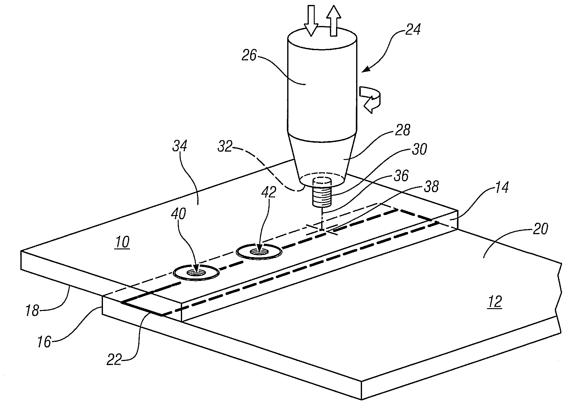
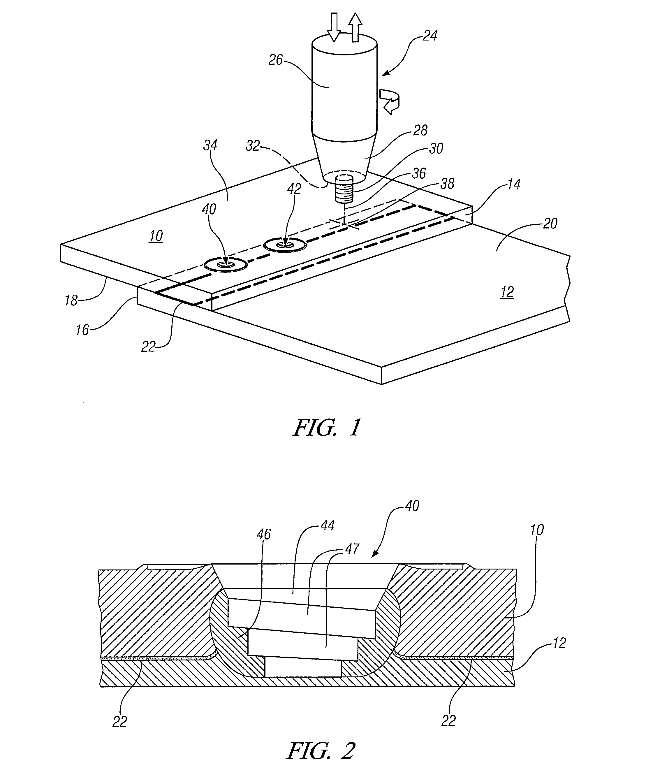
[0019]FSW and FSSW of aluminum alloy to magnesium alloy workpieces often causes the formation of a fairly large amount of brittle, low-melting-point intermetallic phases, which is undesirable for attaining high joint strengths. Melting in FSSW operations causes the stir zone material to stick to the pin tool and thereby only low joint strengths are achieved.

[0020]Friction stir spot welding of 1.6 mm thick, AA5754 aluminum alloy strips to 1.3 mm thick, AZ31 magnesium alloy strips was conducted. The pieces were supported on a steel anvil. A friction stir tool having a probe height of about 2.4 mm, a probe diameter of about 3 mm and a tool shoulder diameter of about 10 mm was rotated at a speed of 1600 rpm and applied to the aluminum surface at a force of about 8 kN. The probe had a threaded external surface. The probe penetrated through the aluminum strip and into the magnesium strip. The plasticized spot weld was formed in a few seconds and the tool and probe retracted. After a spot ...


PUM

PropertyMeasurementUnit
temperatureaaaaaaaaaa
melting temperaturesaaaaaaaaaa

Abstract

When a friction stir weld tool penetrates the interface of two workpieces of dissimilar metal alloy materials, the resultant weld of the different alloy materials may produce a weak weld joint. Such weak joints are often experienced, for example, when attempting to form spot welds or other friction stir welds between a magnesium alloy sheet or strip and an aluminum alloy sheet or strip. It is discovered that suitable coating compositions placed at the interface of assembled workpieces can alter the composition of the friction stir weld material and strengthen the resulting bond. In the example of friction stir welds between magnesium alloy and aluminum alloy workpieces, it is found that combinations of copper, tin, and zinc, and other powders can strengthen the magnesium-containing and aluminum-containing friction stir weld material.

Description

TECHNICAL FIELD[0001]This invention pertains to the use of friction stir welding in joining dissimilar metal members, such as a magnesium alloy panel and an aluminum alloy reinforcing piece. More specifically, this invention pertains to the placement of an interlayer material such as metallic powder or metallic coating layer compositions between facing surfaces of the different metal-composition members for incorporation into the joint material produced by the friction stir weld tool to increase the strength of the welded joint.BACKGROUND OF THE INVENTION[0002]There are manufacturing applications in which it could be useful to weld members of dissimilar metal compositions to fabricate, for example, relatively light-weight articles. For example, in the manufacture of automotive vehicle body parts it might be desired to bond an aluminum alloy reinforcing strut to a magnesium alloy panel. Often, such dissimilar metal members are difficult to join by conventional joining techniques such...

Claims


Application Information

Patent Timeline
Patent Type & Authority Applications(United States)
IPC IPC(8): B23K20/12
CPCB23K20/122B23K2203/10B23K20/2333B23K2103/10
Inventor CHEN, YEN-LUNGCHIMBLI, SRI KRISHNAHALL, MARK T.GAYDEN, XIAOHONG Q.SZYMANSKI, ROBERT T.
Owner GM GLOBAL TECH OPERATIONS LLC
Why Eureka
Try Eureka