Method and system for positioning object with adaptive resolution

a positioning object and adaptive resolution technology, applied in the direction of direction finders, instruments, measurement devices, etc., can solve the problems of low accuracy, low system cost, and low accuracy of rf-based approach, so as to reduce the deployment cost of the system and reduce the cost of the system

Inactive Publication Date: 2010-04-15
NEC (CHINA) CO LTD
View PDF6 Cites 66 Cited by
  • Summary
  • Abstract
  • Description
  • Claims
  • Application Information

AI Technical Summary

Benefits of technology

[0018]In the present invention, the application scenario is divided into two kinds of regions: “Hot Area” where highly accurate positioning is required (for example, in centimeter level), and “General Area” where low positioning accuracy is acceptable (in meters or room level). As an example, ultrasonic positioning device (i.e. US positioning device) is deployed in “Hot Area” for highly accurate localization and RF positioning device is deployed in “General Area” for larger resolution localization. In addition, an online training algorithm is proposed in the present invention, in which the RF model (i.e. RF radio map) can be trained from the real-time position results from the US positioning device. In more details, in the area that can be covered by the US positioning device, i.e. the Hot Area, the more accurate US positioning results can be used to label the RF signal strength (RSS) data, while in the general area, the RSS data will not be labeled because the area cannot be covered by the US positioning device. Then, a semi-supervised learning algorithm can be conducted to train the RF radio map by using the labeled and unlabeled RSS data in real time. In this way, the human calibration efforts for the hybrid positioning system can be reduced.
[0023]Adaptive positioning resolution: based on a positioning fusing method, the system of the present invention can provide different positioning resolutions at different regions.
[0024]Low system cost: the deployment cost of the system can be reduced considerably since dense US positioning devices are not needed.
[0026]Easier area division strategy: based on the user requirement or heuristic rules, it is easy to define the Hot Area. Also, the Hot Area can be accurately covered by adjusting the US positioning system.

Problems solved by technology

However, there are some common limitations to the existing positioning systems.
For example, US-based localization can achieve high accuracy but small scale, and on the other hand, RF-based approach provides large scale but low accuracy.
The first point to be noted here is that Global Positioning System (GPS) can provide the object's location information with the accuracy of several ten meters outdoors, however, in indoor environment GPS does not work well since the positioning result of GPS degrades dramatically by multi-path effect and signal obstruction.
From the Table.1 we can basically conclude that infrared based location systems is rarely used due to low accuracy and vulnerability to natural light; and that RF systems which use signal strength to estimate location can not yield satisfactory results because RF propagation within buildings deviates heavily from empirical mathematical models.
Regarding US-based Bat system, it is awkward to deploy such a networked system into practical scenario, needing high installation and maintenance costs.
In particular, since at least three distance samples are needed to estimate the object's position, very dense ultrasound sensors need to be deployed into building so that system cost is high.
On the other hand, Although US positioning approach can achieve highly accuracy, high density of US positioning devices will cause high deployment cost.
In summary, any existing positioning methods as described above cannot work cost-effectively to achieve high-precision and high-efficiency positioning in an environment where different positioning resolution is required at different regions.

Method used


Image

  • Method and system for positioning object with adaptive resolution
  • Method and system for positioning object with adaptive resolution
  • Method and system for positioning object with adaptive resolution

Examples


Embodiment Construction

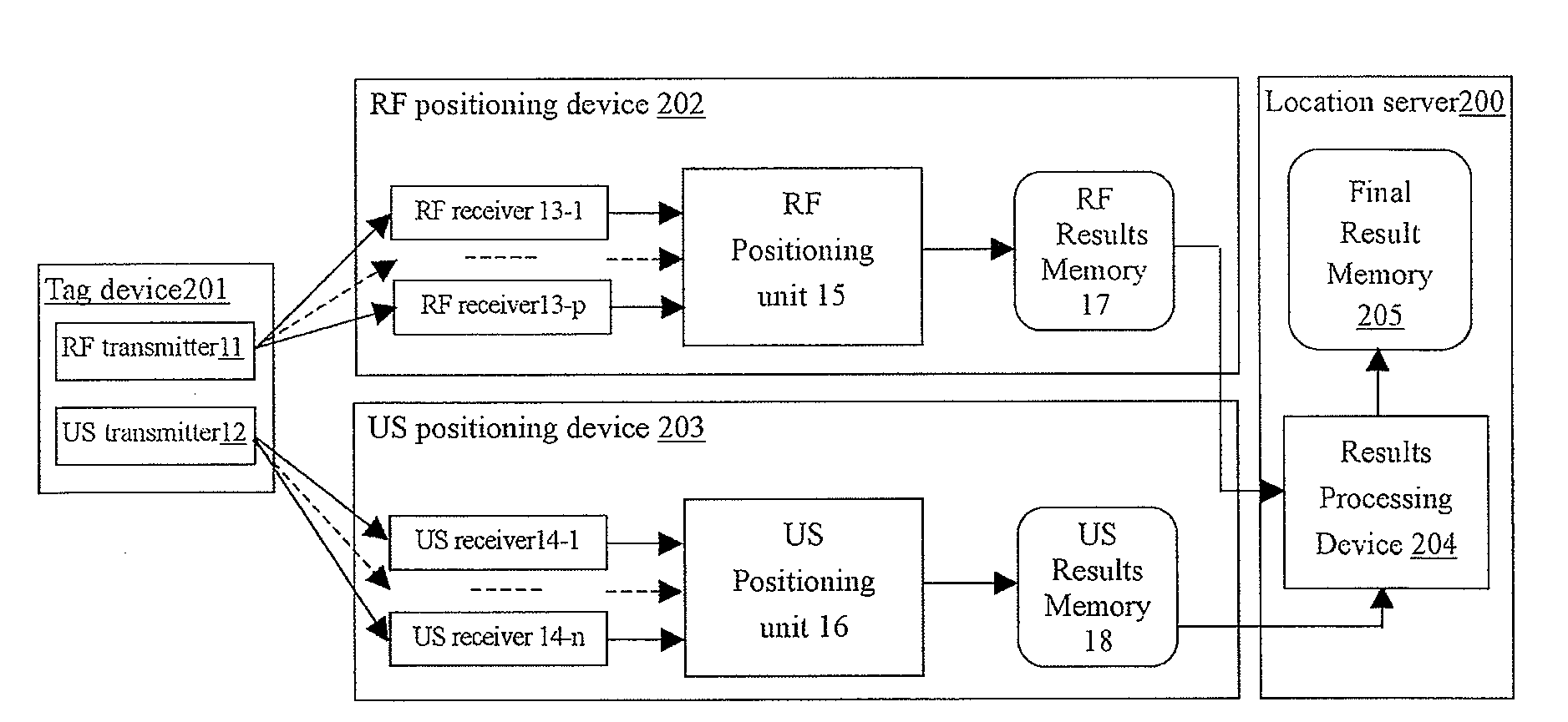
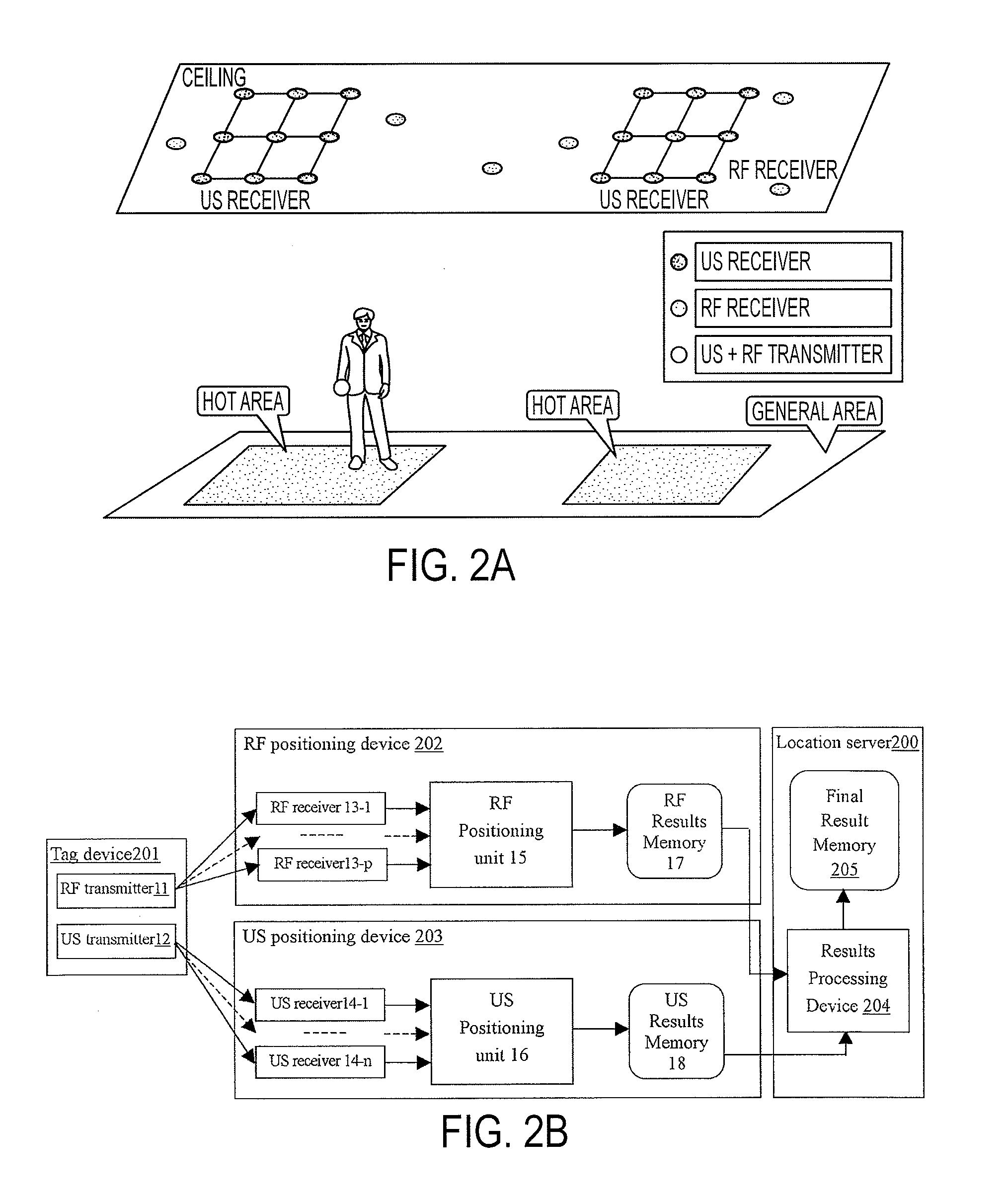
[0041]FIG. 2A shows a hybrid positioning system according to the present invention, which can provide adaptive positioning resolution for location based services. The space to be detected is divided into two kinds of areas: “Hot Area” and “General Area”. In the “Hot Area”, highly accurate positioning (for example, in centimeter level) is required, while in the “General Area”, low positioning accuracy (in meters or room level) is acceptable. Ultrasonic (US) receivers are deployed over the “Hot Area” for highly accurate localization and RF receivers are deployed over the whole detected space (either of the “Hot Area” and the “General Area”) for larger resolution localization.

[0042]When designing hybrid positioning system of the present invention, the following two aspects are considered:

[0043]1. From the application aspect, in location-based access control, it is usually the case that people may require different positioning granularities at different areas. For example, at the intere...


PUM


Abstract

The present invention provides a method and system for positioning an object with adaptive resolution. The method comprises: dividing a space to be detected into Hot Area and General Area; arranging, according to the positions of Hot Area and General Area, high-resolution positioning signal (US) transceivers and low-resolution positioning signal (RF) transceivers, wherein the detection scope of the low-resolution positioning signal transceivers covers the space and the detection scope of the high-resolution positioning signal transceivers covers the Hot Area; and when the object moving in the space, fusing the detection results from the high-resolution positioning signal transceivers and the low-resolution positioning signal transceivers to determine the position of the object with adaptive resolution. With the system of the present invention, for different areas, the object can be positioned with different positioning resolutions (precisions or granularities). Also, since it is not necessary to use a great deal of high-precision positioning devices, the system cost can be reduced considerably.

Description

FIELD OF THE INVENTION[0001]The present invention is generally related to a positioning system and position sensing. More specifically, the present invention relates to a hybrid positioning method and system for combining high-precision positioning technology, e.g. ultrasound (US) positioning, with low-precision positioning technology, e.g. radio frequency (RF) positioning to provide adaptive positioning resolution for location-based services.BACKGROUND[0002]Undoubtedly, location information is a fundamental context to be utilized to extract the geographical relationship between the users and the environments to further understand the user behaviors. The importance and promise of location-aware applications has led to the design and implementation of systems for providing location information, particularly in indoor and urban environments. Currently, there is an increasing market need for accurately tracking of people and assets in real time, in many different application scenarios ...

Claims


Application Information

Patent Timeline
Patent Type & Authority Applications(United States)
IPC IPC(8): G01S5/02G01S3/80G01S1/24
CPCG01S5/0252G01S5/18G01S5/14G01S5/0263G01S5/0264G01S5/02525G01S5/02527
Inventor ZHAO, JUNHUIWANG, YONGCAI
Owner NEC (CHINA) CO LTD
Why Eureka
Try Eureka