Method for manufacturing a magneto-resistance effect element and magnetic recording and reproducing apparatus

a technology of magnetoresistance and effect elements, which is applied in the direction of magnetic materials for record carriers, magnetic bodies, instruments, etc., can solve the problems of reducing resistance, converting weak magnetic fields, and high resistance in tmr elements

Inactive Publication Date: 2010-04-15
KK TOSHIBA +1
View PDF99 Cites 20 Cited by
  • Summary
  • Abstract
  • Description
  • Claims
  • Application Information

AI Technical Summary

Benefits of technology

[0016]According to an aspect of the invention, there is provided a method for manufacturing a magneto-resistance effect element having a first magnetic layer including a ferromagnetic material, a second magnetic layer including a ferromagnetic material and a spacer layer provided between the first magnetic layer and the second magnetic layer, the spacer layer having an insulating layer and a conductive portion penetrating through the insulating layer, the method including: forming a film to be a base material of the spacer layer; performing a first treatment using a gas including at least one of oxygen molecules, oxygen atoms, oxygen ions, oxygen plasma and oxygen radicals on the film; and performing a second treatment using a gas including at least one of hydrogen molecules, hydrogen atoms, hydrogen ions, hydrogen plasma, hydrogen radicals, deuterium molecules, deuterium atoms, deuterium ions, deuterium plasma and deuterium radicals on the film submitted to the first treatment.
[0017]According to another aspect of the invention, there is provided a method for manufacturing a magneto-resistance effect device having a first magnetic layer including a ferromagnetic material, a second magnetic layer including a ferromagnetic material and a spacer layer provided between the first magnetic layer and the second magnetic layer, the spacer layer having an insulating layer and a conductive portion penetrating through the insulating layer, the method including: forming a film to be a base material of the spacer layer; performing a first treatment using a gas including at least one of oxygen molecules, oxygen atoms, oxygen ions, oxygen

Problems solved by technology

However, when a head size becomes small with increasing of the recording density in a HDD, a heat or the like become problem and the TMR element, in which a sense current is flowed to the film in the direction perpendicular to the film surface thereof was put to practical use next.
However, the resistance in the TMR element is usually high because it uses a tunneling current through an insulating barrier.
It will become problem not to decrease the resistance of the element in future when

Method used


Image

  • Method for manufacturing a magneto-resistance effect element and magnetic recording and reproducing apparatus
  • Method for manufacturing a magneto-resistance effect element and magnetic recording and reproducing apparatus
  • Method for manufacturing a magneto-resistance effect element and magnetic recording and reproducing apparatus

Examples


first embodiment

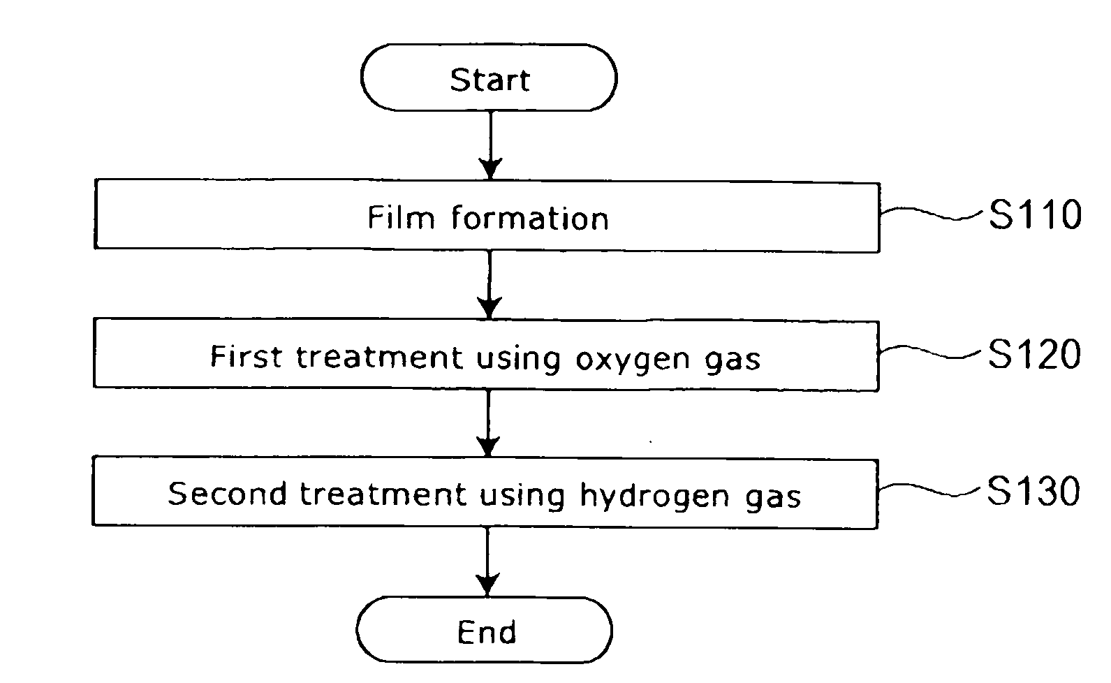
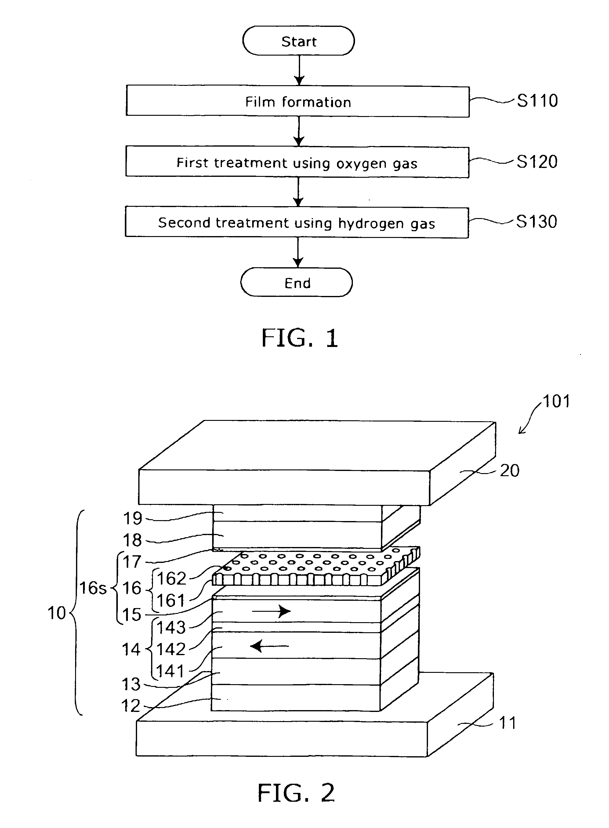
[0058]FIG. 1 is a flow chart illustrating a method for manufacturing a magneto-resistance effect element according to a first embodiment of this invention.

[0059]FIG. 2 is a schematic perspective view illustrating a configuration of a magneto-resistance effect element to which the method for manufacturing a magneto-resistance effect element according to a first embodiment of this invention is applied.

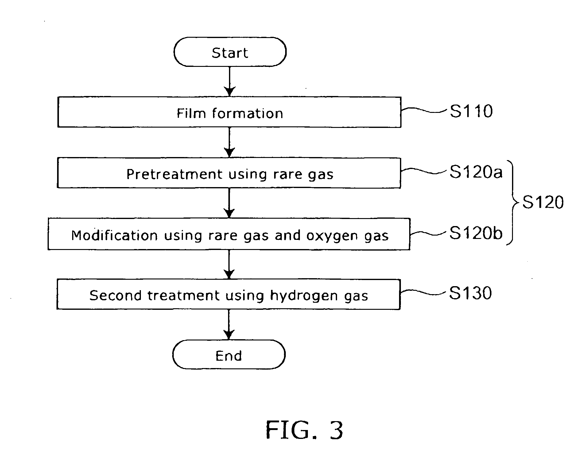
[0060]FIG. 3 is a flow chart illustrating a specific example of the method for manufacturing a magneto-resistance effect element according to a first embodiment of this invention.

[0061]FIGS. 4A to 4D are schematic sectional views following step sequence illustrating the method for manufacturing a magneto-resistance effect element according to a first embodiment of this invention.

[0062]That is, FIG. 4A represents the first step, and FIG. 4B represents the step following the step of FIG. 4A, and FIG. 4C represents the step following the step of FIG. 4B, and FIG. 4D represents the step foll...

first example

[0105]FIG. 6 is a graph illustrating a characteristic of the magneto-resistance effect element by the method for manufacturing a magneto-resistance effect element according to the first example of this invention.

[0106]That is, FIG. 6 illustrates the CuO amount and the MR variation ratio (MR) in the spacer layer 16 in the magneto-resistance effect element 101a produced by the manufacturing method of a first example according to this embodiment and those of the magneto-resistance effect element 109 of the first comparative example. The horizontal axis of this figure represents CuO amount and the vertical axis represents MR variation ratio (MR).

[0107]Here, for the CuO amount, the CuO count number in the spacer layer 16 is evaluated by a 3-dimension atom probe microscope, and standardized so that the CuO count number of the first comparative example is 1.

[0108]The structure and manufacturing condition of the magneto-resistance effect films 10 of the magneto-resistance effect element 101...

second embodiment

[0214]FIG. 10 is a flow chart illustrating a method for manufacturing a magneto-resistance effect element according to a second embodiment of this invention.

[0215]As shown in FIG. 10, in the method for manufacturing a magneto-resistance effect element according to a second embodiment of this invention, after the first step (Step S110), the second step (Step S120) and the third step (Step S130), which are explained with respect to FIG. 1, further a fourth step (Step S140) is carried out.

[0216]Also in this step, the second step (Step S120) may include the PIT step (Step S120a illustrated in FIG. 3) and the IAO step (Step S120b illustrated in FIG. 3).

[0217]In the fourth step, the film submitted to the second treatment is submitted to the third treatment of at least any one of irradiation of rare gas ion, irradiation of rare gas plasma, and heating.

[0218]As the third treatment, the insulating layer 161 and the conductive portion 162 are submitted to, for example, irradiation of Ar ion b...


PUM

PropertyMeasurementUnit
Timeaaaaaaaaaa
Poweraaaaaaaaaa
Poweraaaaaaaaaa

Abstract

A method for manufacturing a magneto-resistance effect element is provided. The magneto-resistance effect element includes a first magnetic layer including a ferromagnetic material, a second magnetic layer including a ferromagnetic material and a spacer layer provided between the first magnetic layer and the second magnetic layer, the spacer layer having an insulating layer and a conductive portion penetrating through the insulating layer. The method includes: forming a film to be a base material of the spacer layer; performing a first treatment using a gas including at least one of oxygen molecules, oxygen atoms, oxygen ions, oxygen plasma and oxygen radicals on the film; and performing a second treatment using a gas including at least one of hydrogen molecules, hydrogen atoms, hydrogen ions, hydrogen plasma, hydrogen radicals, deuterium molecules, deuterium atoms, deuterium ions, deuterium plasma and deuterium radicals on the film submitted to the first treatment.

Description

CROSS-REFERENCE TO RELATED APPLICATIONS[0001]This application is based upon and claims the benefit of priority from the prior Japanese Patent Application No. 2008-249226, filed on Sep. 26, 2008; the entire contents of which are incorporated herein by reference.BACKGROUND OF THE INVENTION[0002]1. Field of the Invention[0003]This invention relates to a method for manufacturing a magneto-resistance effect element and a magnetic recording and reproducing apparatus.[0004]2. Background Art[0005]Performance of a magnetic device, particularly such as a magnetic head is extremely enhanced by using Giant Magneto-Resistive Effect (GMR). Particularly, since a spin valve film (SV film) can exhibit a larger GMR effect, the SV film has developed the magnetic device such as a magnetic head and MRAM (Magnetic Random Access Memory).[0006]The “spin valve” film is laminated films having such a structure as sandwiching a non-magnetic metal spacer layer between two ferromagnetic layers and is called as s...

Claims


Application Information

Patent Timeline
IPC IPC(8): G11B5/706B01J19/08C23C16/44
CPCB82Y10/00B82Y25/00B82Y40/00C23C8/36C23C14/5833C23C14/584H01F10/3259C23C14/5853G01R33/093G11B5/3906G11B2005/3996H01F10/3272H01F41/307C23C14/5846
Inventor YUASA, HIROMIFUKUZAWA, HIDEAKIFUJI, YOSHIHIKOMURAKAMI, SHUICHIHARA, MICHIKOZHANG, KUNLIANGLI, MINSCHRECK, ERHARD
Owner KK TOSHIBA
Why Eureka
Try Eureka