Soft magnetic alloy, magnetic component using the same, and thier production methods

a soft magnetic alloy and magnetic component technology, applied in the direction of magnetic bodies, transformers/inductances, magnetic cores, etc., can solve the problems of low amorphous phase forming ability limited use of fe-based amorphous materials, unsuitable commercial materials, etc., to achieve excellent soft magnetic properties and high forming capability

Active Publication Date: 2010-04-22
TOKIN CORP +2
View PDF7 Cites 68 Cited by
  • Summary
  • Abstract
  • Description
  • Claims
  • Application Information

AI Technical Summary

Benefits of technology

[0017]According to the present invention, there can be provided a soft magnetic alloy capable of depositing an amorphous phase or nanocrystals with an excellent soft magnetic property and a high capability of forming an amorphous phase
[0018]Furthermore, there can be provided a ribbon and powder using such a soft magnetic alloy, a wound magnetic core and a multilayer magnetic core using such a ribbon, and a dust core using such powder. Additionally, an inductor using such a core can be provided.

Problems solved by technology

However, those materials have the following problems.
However, an Fe-based amorphous material has a low capability of forming an amorphous phase.
Therefore, an Fe-based amorphous material is limitedly used for ribbons having a thickness of 20 μm to 30 μm produced by a single-roll liquid quenching method or the like.
However, a Co-based amorphous material has disadvantages in that it has a saturation magnetic flux density as low as that of a ferrite, includes a principal component of Co, which is expensive, and is thus unsuitable for commercial materials.
Because those materials have a low Fe content, the saturation magnetic flux density of those materials is greatly lowered to about 1.2 T. Furthermore, since those materials employ an expensive material such as Ga and Co, they are not preferable in the industrial aspect as with a Co-based amorphous material.
However, the aforementioned nanocrystalline materials generally have a low capability of forming an amorphous phase.
Furthermore, powder cannot directly be produced by a method such as a water atomization method having a relatively low cooling rate.
However, since a pulverization process is added, a manufacturing efficiency of a dust core is lowered.
Additionally, it is difficult to control the grain diameter of powder in pulverization, and particles of the powder cannot be made spherical.
Accordingly, it is difficult to improve the formability and the magnetic properties.
In any case, conventional compositions cannot provide a magnetic core material having an excellent soft magnetic property, a capability of forming an amorphous phase that is high enough to directly produce powder, and a high saturation magnetic flux density.[Non-Patent Document 1] Baolong Shen, Chuntao Chang, and Akihisa Inoue, “Formation, ductile deformation behavior and soft-magnetic properties of (Fe,Co,Ni)—B—Si—Nb bulk glassy alloys,” Intermetallics, 2007, Volume 15, Issue 1, p.

Method used


Image

  • Soft magnetic alloy, magnetic component using the same, and thier production methods
  • Soft magnetic alloy, magnetic component using the same, and thier production methods
  • Soft magnetic alloy, magnetic component using the same, and thier production methods

Examples


examples 259-266

[0104]Materials of Fe, B, Fe75P25, Si, Fe80C20, Cu, Nb, and Cr were respectively weighed so as to provide alloy compositions of Examples 259-266 of the present invention as listed in Table 11 below and put into an alumina crucible. The crucible was placed within a vacuum chamber of a high-frequency induction heating apparatus, which was evacuated. Then the materials were melted within a reduced-pressure Ar atmosphere by high-frequency induction heating to produce master alloys. The master alloys were processed by a single-roll liquid quenching method so as to produce continuous ribbons having a thickness of 25 μM, a width of about 5 mm, and a length of about 10 m. For each ribbon, the resistivity was evaluated with a resistance meter. Furthermore, the ribbons were used to produce a wound magnetic core having an inside diameter of 15 mm, an outside diameter of 25 mm, and a height of 5 mm. The initial magnetic permeability was evaluated at 10 kHz and 100 kHz, respectively, with an imp...

example 288

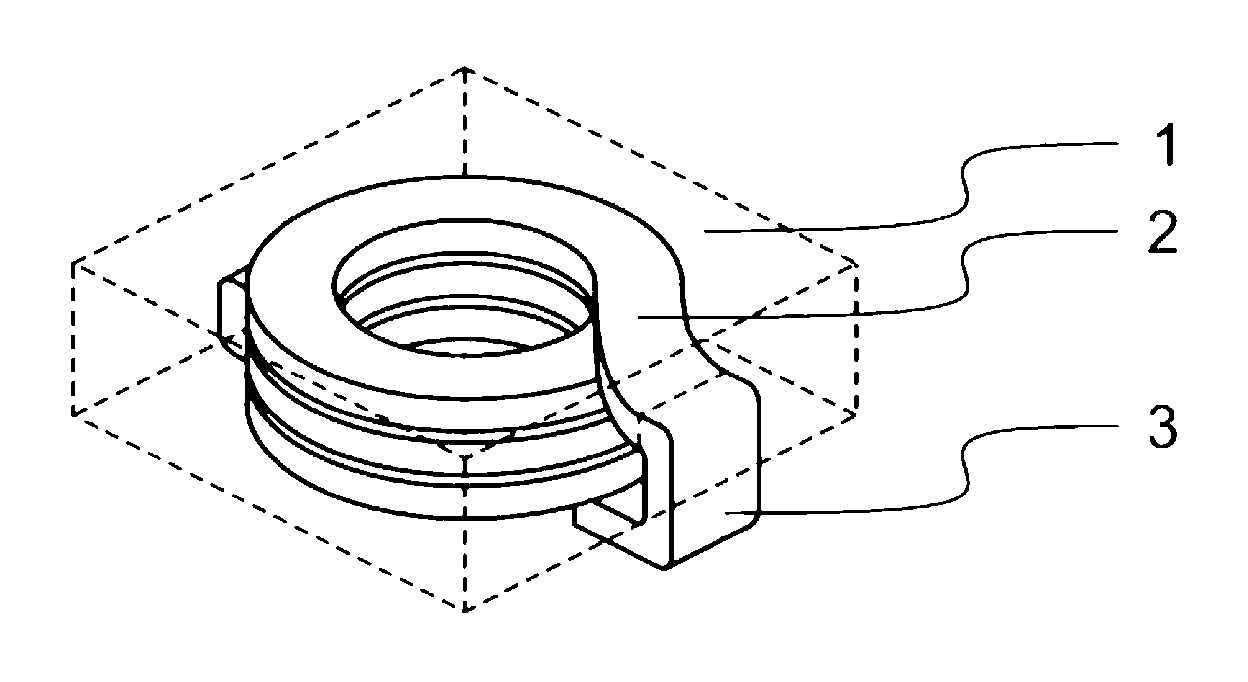
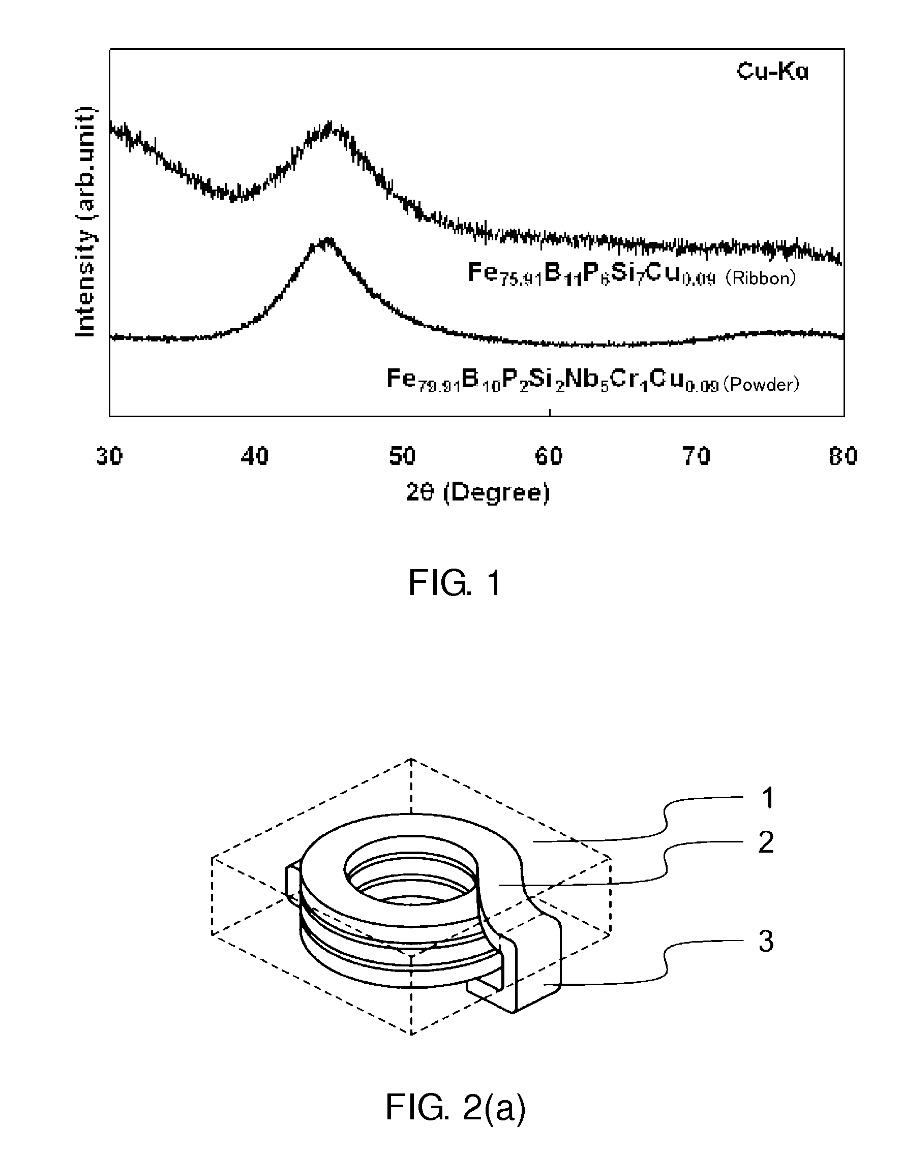
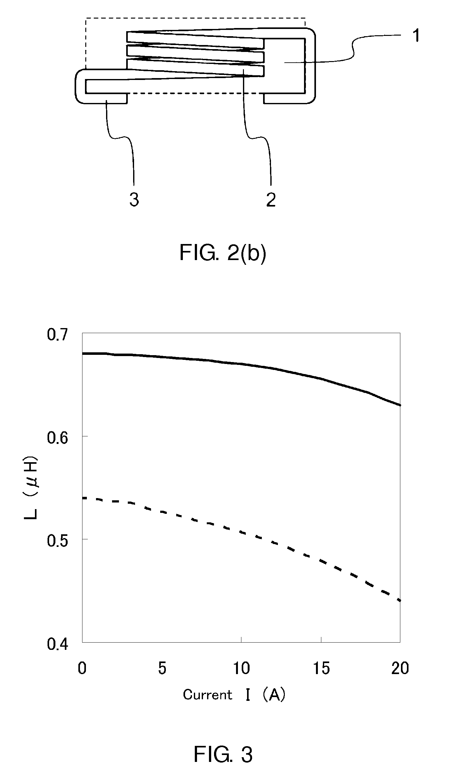
[0114]Next, there will be described the evaluation results of an inductor produced by providing a coil on a dust core formed of soft magnetic powder according to the present invention. The produced inductor was an integrated inductor in which a coil is provided inside of a dust core. FIGS. 2(a) and 2(b) are views showing the inductor of this example. FIG. 2(a) is a perspective view in which the coil can be seen through the inductor, and FIG. 2(b) is a side view in which the coil can similarly be seen through the inductor. In FIGS. 2(a) and 2(b), the reference numeral 1 denotes the dust core, the outline of which is shown by the dashed lines, the reference numeral 2 denotes the coil, and the reference numeral 3 denotes a terminal for surface mounting. First, a sample weighed so as to have the composition of Fe79.9Si2B10P2Nb5Cr1Cu0.09 shown in Example 2 was prepared as a material according to the present invention. This sample was then placed in an alumina crucible, subjected to evacu...


PUM

PropertyMeasurementUnit
average grain diameteraaaaaaaaaa
thicknessaaaaaaaaaa
diameteraaaaaaaaaa

Abstract

A soft magnetic alloy contains P, B, and Cu as essential components. As a preferred example, an Fe-based alloy contains Fe of 70 atomic % or more, B of 5 atomic % to 25 atomic %, Cu of 1.5 atomic % or less (excluding zero), and P of 10 atomic or less (excluding zero).

Description

TECHNICAL FIELD[0001]This invention relates to a soft magnetic alloy such as soft magnetic powder or a soft magnetic ribbon, a magnetic core and an inductor using the soft magnetic alloy, and a method of manufacturing the same.BACKGROUND ART[0002]Miniaturization and energy conservation of electronic devices have been demanded more intensively than before because of recent development of portable devices and recent needs for less environmental loads in consideration of the global warming. Accordingly, miniaturization, a higher frequency, a higher efficiency, a smaller thickness, and the like have been demanded more intensively than before with regard to magnetoelectronic parts used for electronic devices such as transformers and choke coils. Heretofore, Mn—Zn, Ni—Zn ferrite, and the like have frequently been used as a material for magnetoelectronic parts. However, those materials have recently been replaced with multilayer magnetic cores, wound magnetic cores, and dust cores of a mag...

Claims


Application Information

Patent Timeline
Patent Type & Authority Applications(United States)
IPC IPC(8): H01F27/24C22C45/02C22C38/16H01F1/01C22C38/00C22C30/02B22F1/00B22F7/04
CPCB22F9/08H01F1/15333B22F2009/048B22F2998/10C21D6/00C21D6/004C21D6/007C21D8/1211C22C33/0207C22C38/002C22C38/16C22C45/02C22C2200/02C22C2202/02H01F1/15308H01F1/15325H01F1/15375H01F27/255H01F27/292H01F41/0226H01F2017/046B22F2003/248B22F1/0085B22F1/0059B22F3/02B22F3/24B22F1/08B22F1/10B22F1/142H01F1/16
Inventor URATA, AKIRIMATSUMOTO, HIROYUKIMAKINO, AKIHIRO
Owner TOKIN CORP
Why Eureka
Try Eureka