Mixed Flow Turbine or Radial Turbine

a technology of mixing flow turbine and radial turbine, which is applied in the direction of liquid fuel engines, vessel construction, marine propulsion, etc., can solve the problems of incidence loss, and achieve the effects of suppressing the increase of incidence loss due to unbalanced load, reducing the rate of change, and reducing the load applied on the blade surfa

Active Publication Date: 2010-04-22
MITSUBISHI HEAVY IND LTD
View PDF4 Cites 12 Cited by
  • Summary
  • Abstract
  • Description
  • Claims
  • Application Information

AI Technical Summary

Benefits of technology

[0030]The rate of change of the relative flow velocity W toward the rotational direction becomes greater as the radial direction position becomes smaller, that is to say, since it has a rate of change toward the rotational direction, the smaller the radial direction position becomes, that is to say, the closer to the hub side, the greater the rate of change becomes.
[0031]According to the present invention, the inflected section is configured such that the curvature of the camber line becomes smaller closer to the outer diameter side from the hub side. As a result, the load applied on the blade surface can be significantly reduced on the hub side, where the load is significant, while the load reduction rate gradually decreases toward the outer diameter side, where the load is smaller.
[0032]Therefore, the load Fr in the height direction of the blade can be made substantially uniform, and an incidence loss increase due to unbalanced load can be suppressed.
[0033]As a result, incidence loss can be reduced across the entire region in the height direction of the blade.
[0034]According to the present invention, on the leading edge of the blade there is provided the inflected section that is inflected so that the camber line on the section surface along the outer circumference surface of the hub is concave-curved to the rotational direction side. Therefore a rapid increase in load applied to the blade at the leading edge section can be prevented.
[0035]The occurrence of a leak flow from the pressure surface side to the suction surface side due to this load can be suppressed, and incidence loss can be reduced.

Problems solved by technology

When the angular difference between the leading edge and the gas inflow angle becomes greater in this way, the inflowing gas separates at the leading edge and collision loss becomes greater, resulting in the occurrence of incidence loss.

Method used


Image

  • Mixed Flow Turbine or Radial Turbine
  • Mixed Flow Turbine or Radial Turbine
  • Mixed Flow Turbine or Radial Turbine

Examples


first embodiment

[0064]Hereinafter, a mixed flow turbine 1 according to a first embodiment of the present invention is described, with reference to FIG. 1 through FIG. 7. This mixed flow turbine 1 is used in a turbocharger (turbocharger) for a diesel engine in a motor vehicle.

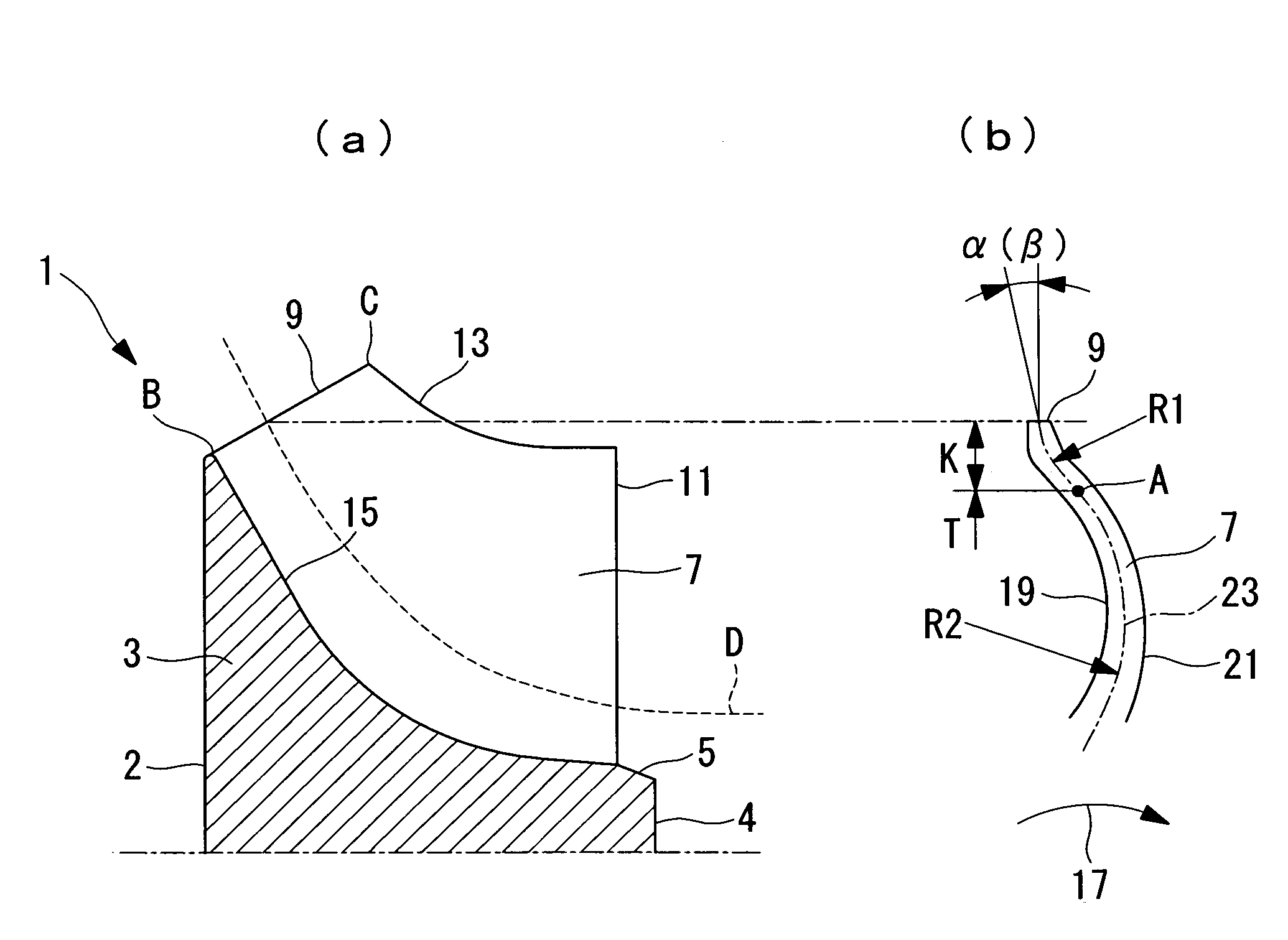
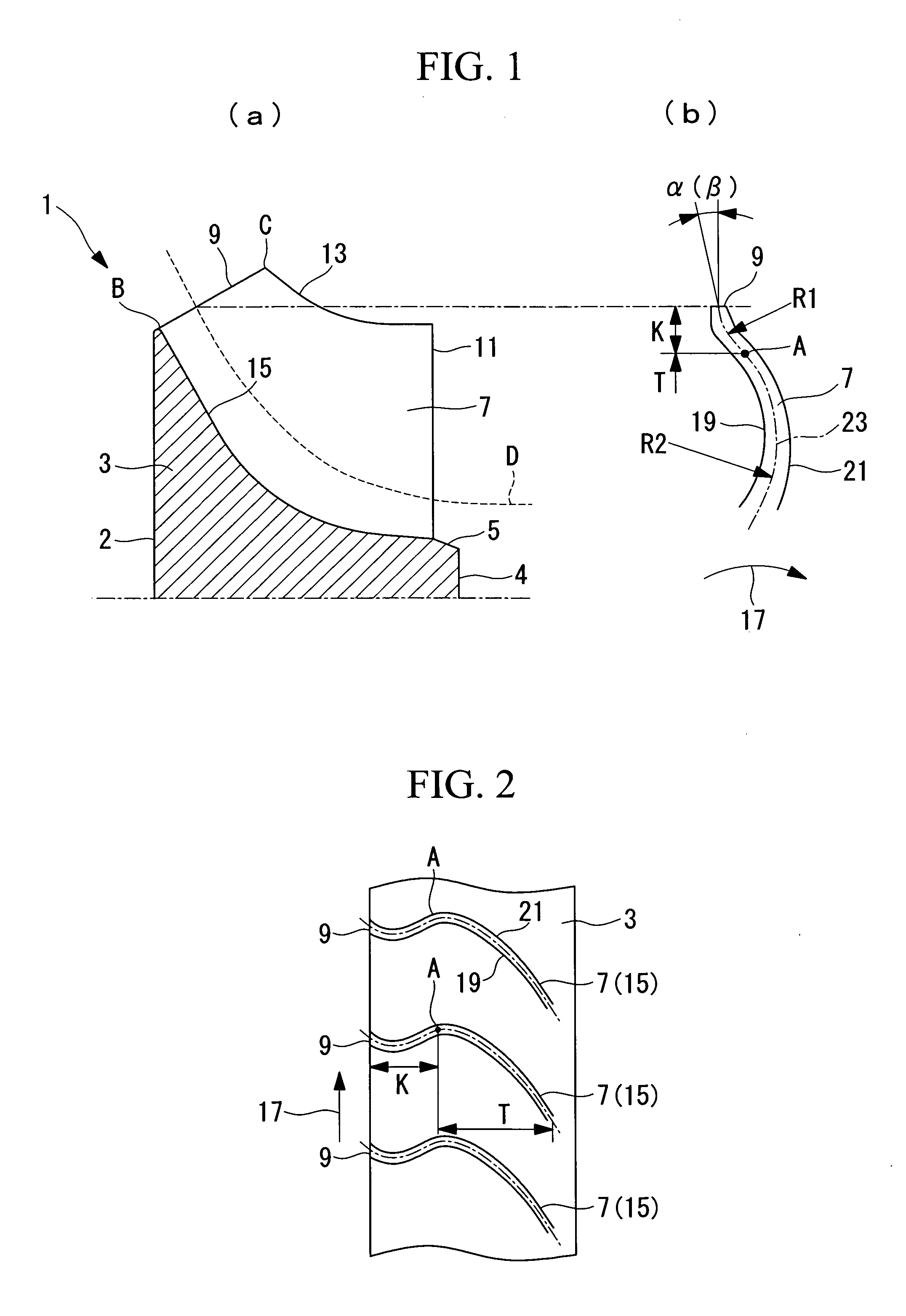
[0065]FIG. 1 shows a blade portion of the mixed flow turbine 1 of the present embodiment, wherein (a) is a partial sectional view showing a meridional plane sectional surface, and (b) is a partial sectional view showing a sectional surface of the blade cut along an outer circumference surface of a hub. FIG. 2 is a spread partial projection drawing of the outer circumference surface of the hub projected on a cylindrical surface.

[0066]The mixed flow turbine 1 is provided with; a hub 3, a plurality of blades 7 provided at substantially equal intervals on an outer circumference surface 5 of the hub 3 in its circumferential direction, and a casing (not shown in the drawing).

[0067]The hub 3 is configured such that it is connected to ...

second embodiment

[0099]Next, a second embodiment of the present invention is described, with reference to FIG. 9.

[0100]FIG. 9 is a partial sectional view of the blade 7 of a mixed flow turbine 1 cut on a section D along the outer circumference surface of the hub 3.

[0101]The mixed flow turbine 1 in the present embodiment differs from the one in the first embodiment in the configuration of the leading edge 9 section of the blade 7. Other constituents are the same as in the first embodiment mentioned above, and repeated descriptions of these are therefore omitted here.

[0102]The same reference symbols are given to members that are the same as in the first embodiment.

[0103]In the present embodiment, a suction surface thickened section 25 is provided on the suction surface 21 side of the leading edge 9 portion, and a pressure surface thickened section 27 is provided on the pressure surface 19 side. That is to say, the blade thickness of the leading edge 9 section is increased.

[0104]In FIG. 9, the suction ...

third embodiment

[0119]Next, a third embodiment of the present invention is described, with reference to FIG. 10 to FIG. 12.

[0120]FIG. 10 is a graph showing changes in the curvature radius R1 of the inflected section K in the height direction of the blade 7. FIG. 11 shows a blade portion of a mixed flow turbine of the present embodiment, wherein (a) is a partial, sectional view showing a meridional plane sectional surface, and (b) through (d) are partial sectional views showing a sectional surface of the blade 7 cut along an outer circumference surface of a hub 3, (b) showing a height position 0.2H, (c) showing a height position 0.5H, and (d) showing a height position 0.8H. FIG. 12 shows a relationship between the relative flow β and the blade angle α.

[0121]The mixed flow turbine 1 in the present embodiment differs from the one in the first embodiment in the configuration of the leading edge 9 section of the blade 7. Other constituents are the same as in the first embodiment mentioned above, and rep...


PUM


Abstract

Intended is to provide a mixed flow turbine or a radial turbine, which can suppress an abrupt increase in a load to be applied to the front edge portion of a blade, thereby to reduce an incidence loss. The mixed flow turbine or the radial turbine comprises a hub (3), and a plurality of blades (7) arranged at substantially equal interval on the outer circumference (5) of the hub (3) and having a warpage (23) curved convexly in the rotating direction, as entirely viewed from the front edge side to the back edge side. Each blade (7) is provided, at its front edge portion, with an inflection point (K), at which the warpage (23) in the section along the outer circumference is curved concavely in the rotating direction.

Description

TECHNICAL FIELD[0001]The present invention relates to a mixed flow turbine or a radial turbine used in a small gas turbine, a turbocharger, an expander, and the like.BACKGROUND ART[0002]In this type of turbine, a plurality of blades is disposed in a radial pattern on the outer circumference of a hub as disclosed for example in Patent Document 1.[0003]The efficiency of a turbine is shown with respect to a theoretical velocity ratio (=U / C0) being a ratio of peripheral velocity U of the blade inlet, to a maximum flow velocity of a working fluid (gas) accelerated by the turbine entry temperature and its compression ratio, that is, a theoretical velocity C0.[0004]A radial turbine has a certain theoretical velocity ratio U / C0 where its efficiency reaches a peak. The theoretical velocity C0 is changed by changes in the state of the gas, such as changes in gas temperature and gas pressure.[0005]When the theoretical velocity C0 changes, the inflow angle of the gas that flows in to a leading ...

Claims


Application Information

Patent Timeline
Patent Type & Authority Applications(United States)
IPC IPC(8): F01D5/14
CPCF01D1/08F01D5/141F05D2220/40F05D2250/711F05D2250/611F05D2250/712F05D2250/713F01D5/048F01D5/12F01D5/14
Inventor YOKOYAMA, TAKAOHIGASHIMORI, HIROTAKAMOTOKI, EBISUSHIRAISHI, TAKASHI
Owner MITSUBISHI HEAVY IND LTD
Why Eureka
Try Eureka