Direct methanol fuel cell system and portable electronic device
- Summary
- Abstract
- Description
- Claims
- Application Information
AI Technical Summary
Benefits of technology
Problems solved by technology
Method used
Image

Examples
first embodiment
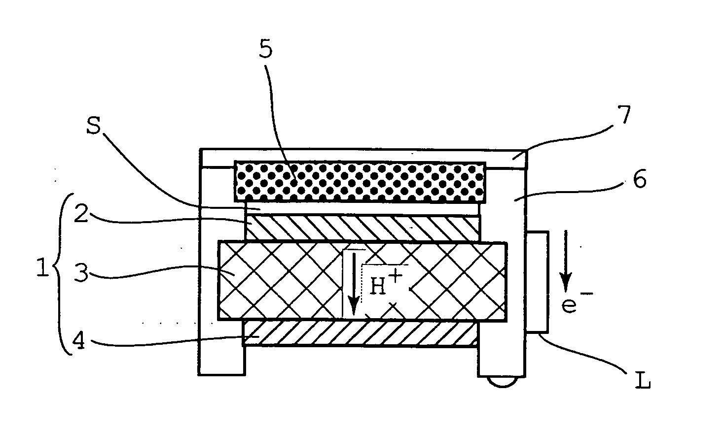
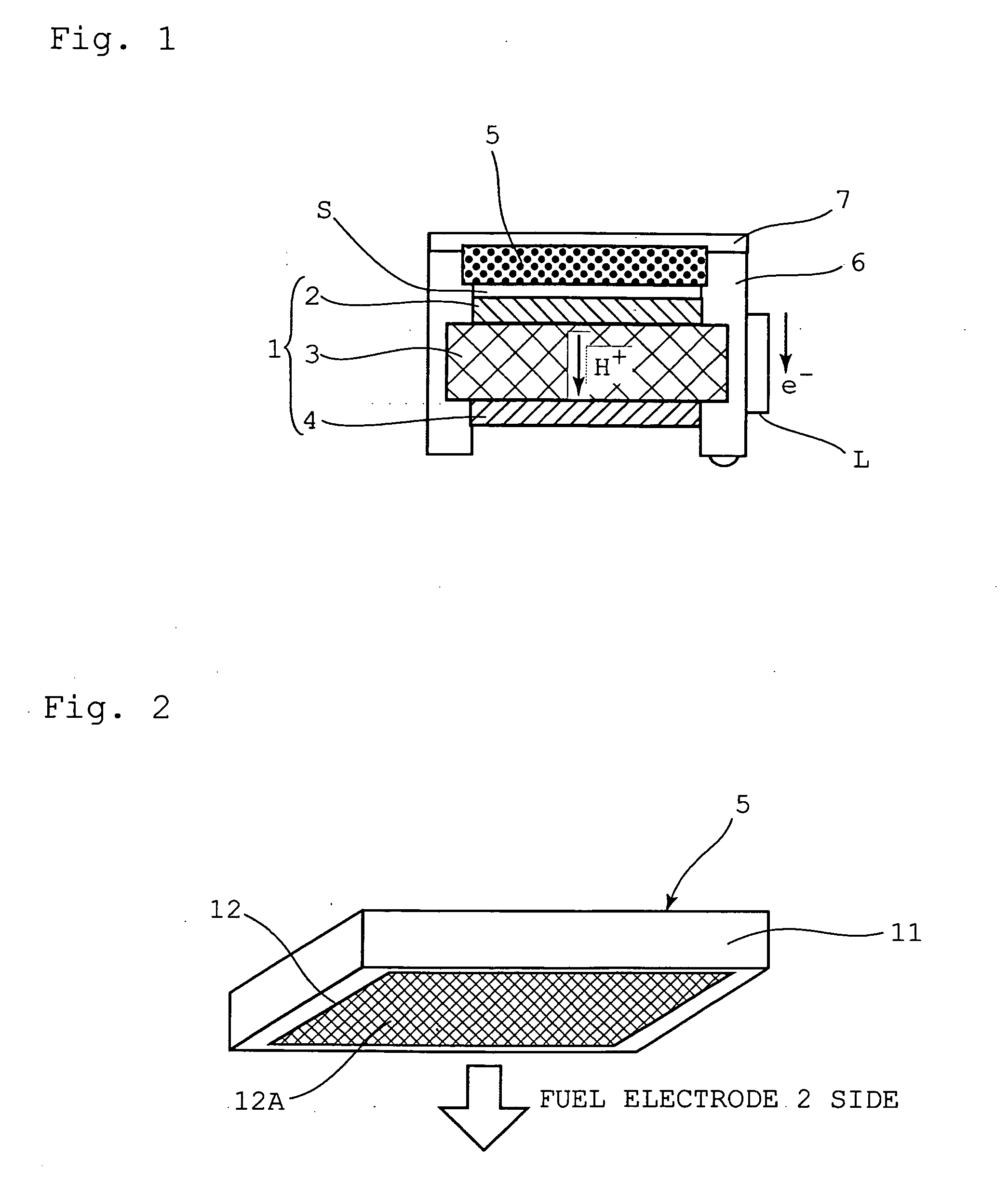
[0069]FIG. 1 is a schematic diagram illustrating a direct methanol fuel cell system according to a first embodiment of the present invention; and FIG. 2 is perspective-view diagram illustrating a solid-state methanol storage container as the fuel container in FIG. 1.
[0070]As illustrated in FIGS. 1 and 2, a fuel cell 1 comprises a fuel electrode 2, an electrolyte membrane 3 and an air electrode 4. The fuel electrode 2 and the air electrode 4 are electrically connected by way of an electric circuit L. A solid-state methanol storage container 5 serving as a fuel container is disposed in the vicinity of the fuel cell 1, on the side of the fuel electrode 2. The fuel cell 1 and the solid-state methanol storage container 5 are fixed so as to be surrounded on four sides by a frame body 6. The top face of the solid-state methanol storage container 5 is covered by an openable and closable cover 7.
[0071]The solid-state methanol storage container 5 comprises a rectangular box-like casing 11, th...
second embodiment
[0088]The configuration of the direct methanol fuel cell system according to a second embodiment of the present invention is similar to that of the direct methanol fuel cell system according to the first embodiment, except that herein a film is formed on the surface of the solid-state methanol. Elements similar to those of the first embodiment will be denoted with identical reference numerals, and a detailed explanation thereof will be omitted.
[0089]In the second embodiment, a film is formed on the surface of the solid-state methanol. This allows controlling the vaporization of the methanol held in a base material such as a porous material or a gel that is in turn confined within the formed film. Methods for forming a film on the surface of solid-state methanol include, for instance, bringing the solid-state methanol into contact with a coating agent.
[0090]Preferred examples of the coating agent include polymer materials having film-forming action, for instance, cellulosic materials...
third embodiment
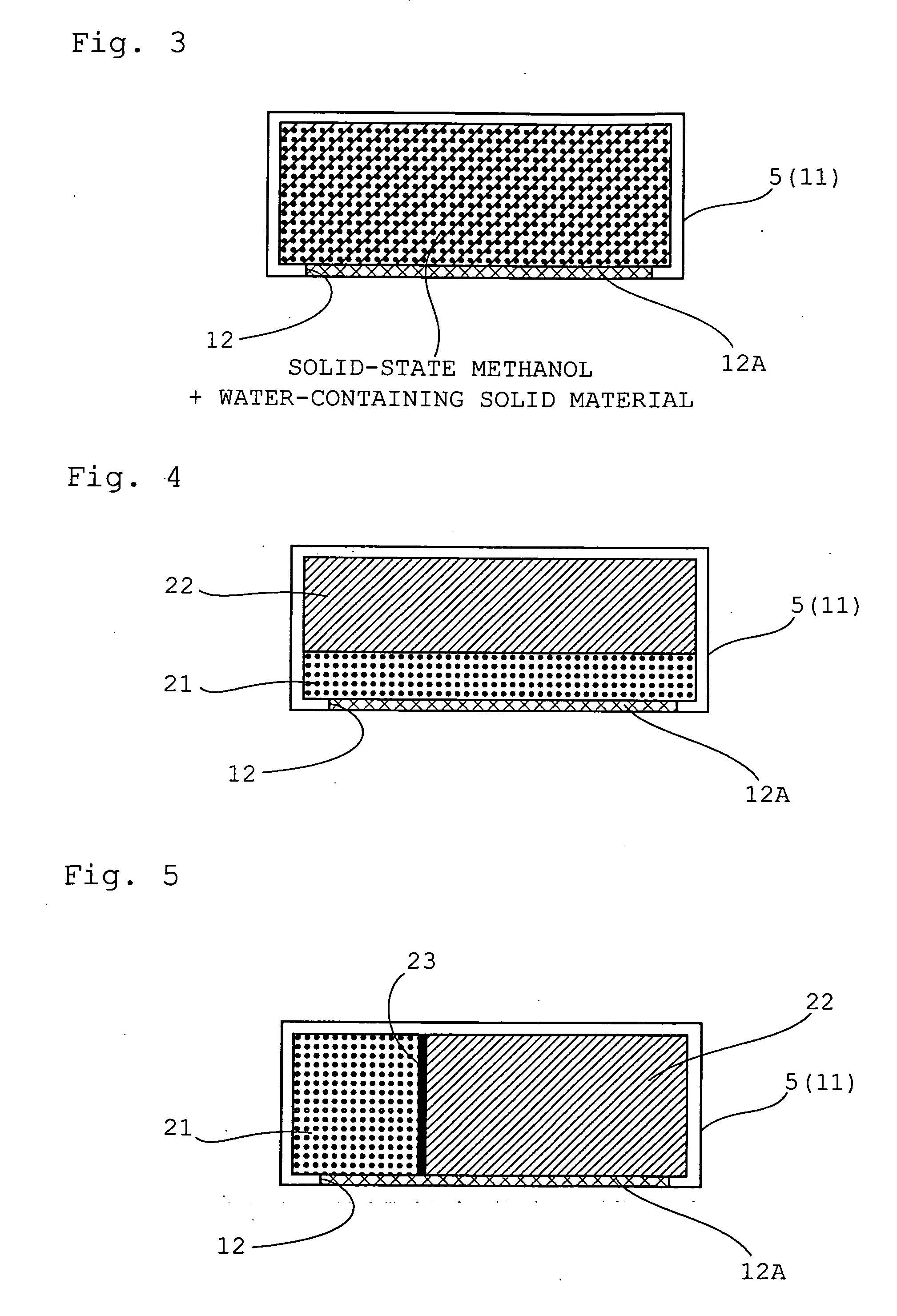
[0105]The configuration of the direct methanol fuel cell system according to the third embodiment of the present invention is similar to that of the direct methanol fuel cell system according to the first embodiment, except that herein the storage container 5 is packed with both solid-state methanol and a water-containing solid material. Elements similar to those of the first embodiment will be denoted with identical reference numerals, and a detailed explanation thereof will be omitted.
[0106]In the third embodiment, the storage container 5 comprises a rectangular box-like casing 11, the interior of which is packed with solid-state methanol resulting from making methanol into a solid state, and with a water-containing solid material. An opening 12 formed on the lower face side of the storage container 5 is divided by a synthetic resin mesh 12A. The solid-state methanol and water-containing solid material are thus held in a homogeneously mixed state, with secured air permeability as ...
PUM
 Abstract
Description
Claims
Application Information
 - Generate Ideas
- Intellectual Property
- Life Sciences
- Materials
- Tech Scout
- Unparalleled Data Quality
- Higher Quality Content
- 60% Fewer Hallucinations
Browse by: Latest US Patents, China's latest patents, Technical Efficacy Thesaurus, Application Domain, Technology Topic, Popular Technical Reports.
© 2025 PatSnap. All rights reserved.Legal|Privacy policy|Modern Slavery Act Transparency Statement|Sitemap|About US| Contact US: help@patsnap.com