System and method for use of a vehicle back-up camera as a dead-reckoning sensor

a technology of dead-reckoning sensor and back-up camera, which is applied in the direction of navigation by terrestrial means, navigation instruments, instruments, etc., can solve the problems of affecting vehicle safety and warranty, affecting vehicle navigation performance, etc., to achieve enhanced vehicle navigation performance, easy to obtain and integrate into the navigation system, and cost-effective

Active Publication Date: 2010-04-22
CSR TECH INC
View PDF9 Cites 22 Cited by
  • Summary
  • Abstract
  • Description
  • Claims
  • Application Information

AI Technical Summary

Benefits of technology

[0004]Systems and methods are disclosed herein to use a vehicle back-up camera as a cost-effective dead-reckoning sensor in a vehicle employing a satellite-based navigation system such as GPS. Since conventional back-up cameras typically display their images using a navigation system's display, the image data from the back-up camera may be easily obtained and integrated into the navigation system. This image data from the camera may be received by the GPS receiver wirelessly or through a wired connection. The image is processed to determine factors such as the speed, heading, or turn-rate of the vehicle to aid the navigation system when the satellite signals are severely degraded. Thus, enhanced vehicle navigation performance can be obtained without adding new sensors and / or connecting to a vehicle data bus.

Problems solved by technology

Satellite-based navigation systems such as the Global Positioning System (GPS) may suffer degradation and outages due to multipath reflectors and blockages between the satellite transmitters and the vehicle's GPS antenna.
This results in degraded performance, particularly in urban canyons and tunnels.
Many of these sensors incur the costs of either a) purchasing the additional sensors and integrating them with the navigation system, or b) getting access to existing sensor data on a vehicle data bus, which can raise vehicle safety and warranty issues.
As such, the cost of acquiring specialized sensors and / or the complication of integrating such sensors into a satellite-based navigation system have prevented widespread adoption of dead-reckoning sensors into vehicle navigation system using GPS.

Method used


Image

  • System and method for use of a vehicle back-up camera as a dead-reckoning sensor
  • System and method for use of a vehicle back-up camera as a dead-reckoning sensor
  • System and method for use of a vehicle back-up camera as a dead-reckoning sensor

Examples


Embodiment Construction

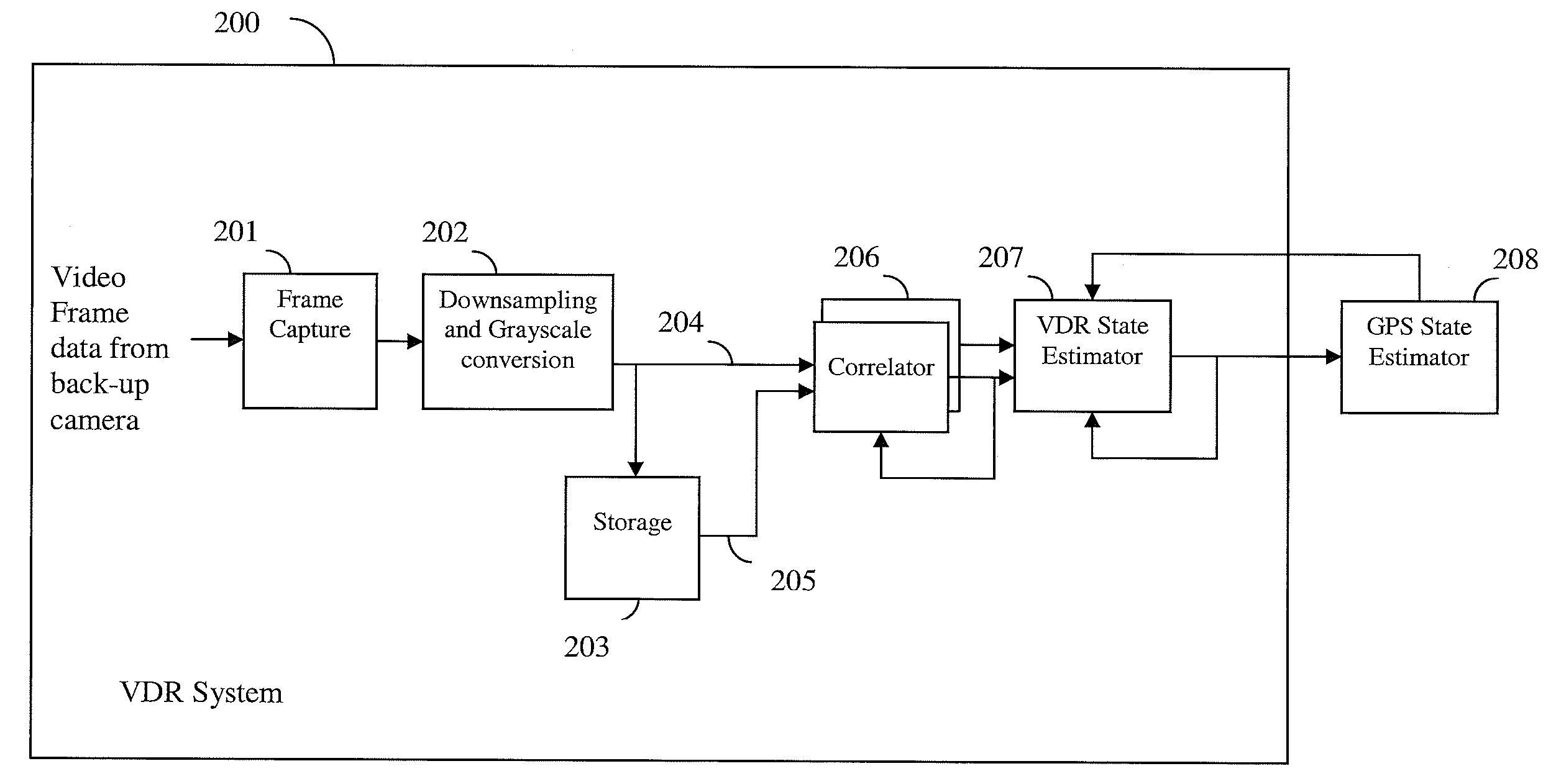
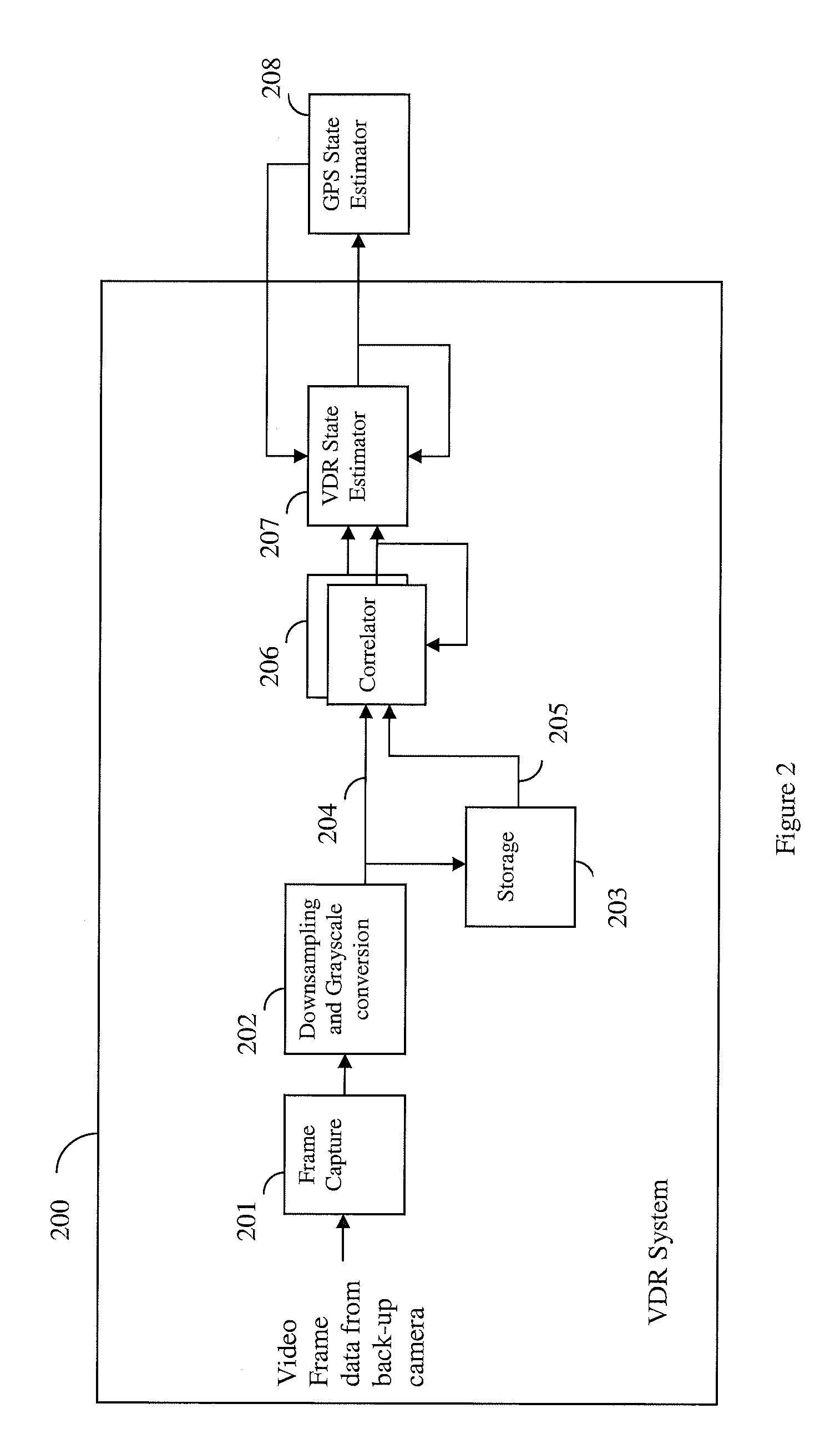
[0025]Systems and methods for using a vehicle back-up camera as a dead-reckoning sensor to aid a satellite-based vehicle navigation system are disclosed. The following examples concern GPS-based navigation systems but it will be appreciated that the systems and methods disclosed herein are widely applicable to other types of satellite-based navigation systems. These systems and methods enable dead-reckoning capability without requiring the addition of any new sensors or the connection to a vehicle data bus.

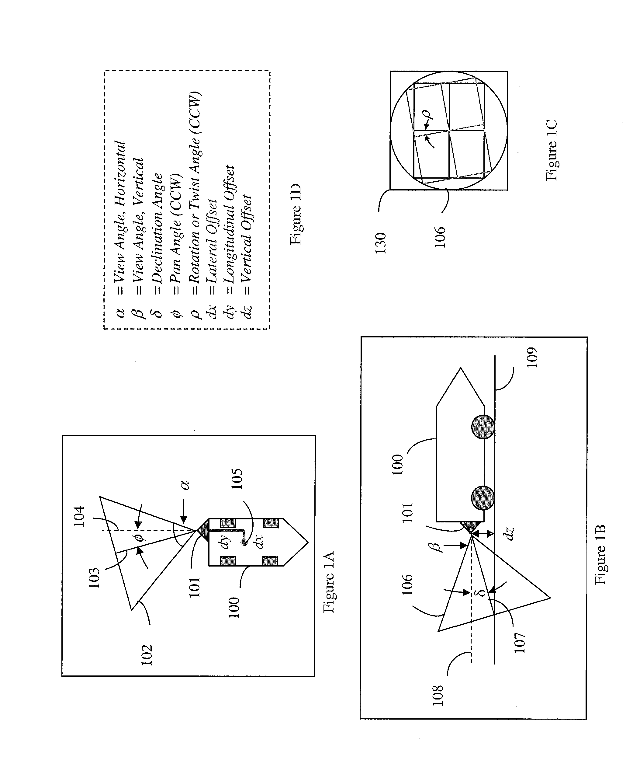
[0026]Turning now to the drawings, FIGS. 1A and 1B show the location and orientation of a back-up camera on a vehicle according to one or more embodiments of the present disclosure. FIG. 1C shows a field of view from the back-up camera according to one or more embodiments of the present disclosure. FIG. 1D is a table of spatial parameters associated with the location and orientation of the back-up camera on the vehicle according to one or more embodiments of the present disclosure...


PUM


Abstract

Systems and methods are disclosed herein to use a vehicle back-up camera as a cost-effective dead-reckoning sensor in satellite-based vehicle navigation systems. Since the back-up camera may already use a display of the navigation system for display, the data from the back-up camera may be easily obtained and integrated into the navigation system. The data from the camera is received by a navigation receiver wirelessly or through a wired connection. The image is processed to determine the speed, heading, turn-rate of the vehicle to aid the satellite-based navigation system if the satellite signals are inadequate. Thus, enhanced vehicle navigation- performance can be obtained without adding new sensors and/or connecting to a vehicle data bus.

Description

TECHNICAL FIELD[0001]The present disclosure relates generally to a system and method for using dead-reckoning sensors to aid in vehicle navigation. Specifically, the present disclosure relates to a system and method for use of a camera as a dead-reckoning sensor to aid a vehicle navigation system employing a satellite-based navigation system.BACKGROUND[0002]Satellite-based navigation systems such as the Global Positioning System (GPS) may suffer degradation and outages due to multipath reflectors and blockages between the satellite transmitters and the vehicle's GPS antenna. This results in degraded performance, particularly in urban canyons and tunnels. To provide navigation updates in the absence of GPS signal reception, a variety of dead reckoning enhancements have been offered as adjuncts to GPS navigation systems. Navigation using dead reckoning involves calculating a current position based upon the heading and distance from a previously known position. Dead-reckoning sensors p...

Claims


Application Information

Patent Timeline
Patent Type & Authority Applications(United States)
IPC IPC(8): G01C21/00G06K9/00
CPCG01C21/005G01S19/45G06K9/00791G01C21/10G01C21/00G06K9/00798G01C21/26G01C21/20G01C21/3658G01C21/04G01C21/3461G06V20/588G06V20/56
Inventor KOENIG, MICHAELBRODIE, KEITH
Owner CSR TECH INC
Why Eureka
Try Eureka