System For Generating Electrical Energy Comprising An Electrochemical Reformer And A Fuel Cell

a technology of electrochemical reformer and fuel cell, which is applied in the field of system for generating electrical energy, can solve the problems of gas phase, polymer electrolyte membrane as separator, and remains under investigation in the membrane field, and achieves the effects of improving the overall energy density of the system, simplifying the complexity of the system, and high flow

Inactive Publication Date: 2010-04-29
RAO VINEET +1
View PDF26 Cites 21 Cited by
  • Summary
  • Abstract
  • Description
  • Claims
  • Application Information

AI Technical Summary

Benefits of technology

[0121]The problem of methanol crossover of conventional DMFCs is avoided, which will save up to 40% methanol fuel and thus result in better overall energy density of the system. The EDMFC 20 avoids the problem of methanol crossover as the H2 gas from the cathode 25 of the electrolyzer 21 can be separated from the liquid methanol using condenser or liquid gas separator assemblies. The separated methanol is then fed back to the anode 24 of the electrolyzer 21 and thus methanol (or fuel) utilization of nearly 100% can be reached. No fuel will be lost in the EDMFC 20 due to crossover. But some fuel will be lost on both side of the electrolyzer 21 due to vaporization. Also the electrochemical effect of a mixed potential at the cathode side caused by crossed-over methanol as it is the case in conventional DMFC will be overcome as well.
[0122]The problem of cathode flooding due to liquid crossover is also avoided in the EDMFC 20, as the oxygen reduction reaction takes place at the separate MEA 35 in a complete gas phase as on the cathode side of a conventional PEMFC. The EDMFC scheme overcomes the cathode performance problems in DMFCs related to the cathode flooding by the crossed-over liquids (water+methanol) through the PEM permeable for liquids. In a conventional DMFC the liquids flood the cathode and thus disrupt the diffusion of oxygen to the catalyst layer, creating a mass transport barrier. In the EDMFC 20 methanol oxidation and oxygen reduction takes place in different cells, namely in the electrolyzer 21 and the fuel cell 34 respectively. The separator 33 separates the H2 from gas-liquids mixture and the purified H2 is then fed to the fuel cell 34. So the fuel cell 34 operates in complete gas phase. Thus the cathode 37 of the EDMFC 20 performs similarly as the cathode of a conventional PEMFC.
[0123]In comparison to conventional DMFCs the EDMFC 20 requires no pressurized operation of the cathode 38 and no high flow stoichiometry. An airflow typical of a conventional PEMFC is sufficient. This simplifies the complexity of the system. In addition the electrical energy required for compressors and blowers operating at elevated pressures can be saved. The power requirement for the compressors can constitute a significant portion of up to 22% of the DMFC output depending on the pressure and air flow stoichiometry of cathode operation. Furthermore, these ancillary units have considerably increased the complexity of conventional DMFCs.
[0124]In conventional DMFCs, operation at higher temperatures causes difficulties due to the excessive water vaporization resulting in heat loss and causes a reduced cathode performance due to a reduced partial pressure of oxygen. These effects necessitate an elevated pressure at the cathode side. To achieve the elevated pressure the use of compressors is required. The heat loss due to water vaporization makes it difficult to operate the DMFC autonomously at elevated temperatures at which the electrode kinetics would improve significantly. The EDMFC 20 does not suffer from these drawbacks, since the liquid phase anodic reaction takes place in the electrolyzer 21, and gas phase H2 / O2 electrochemical reaction takes place in the fuel cell 34. The electrolyzer 21 and the fuel cell 34 are physically separated by the separator 33 and thus water is not available in liquid form in the cathode 37 of the fuel cell 34, unlike the conventional DMFC where the water is present excessively at the cathode and where water is also vaporized leading to heat losses. But the electrolyzer 21 where the liquid phase methanol oxidation reaction takes place can be operated autonomously at high temperatures as the outgoing gas flows of the electrolyzer 21 (CO2 and H2) are very small compared to the air flow of a conventional DMFC (air flow with 80% N2) and therefore can be controlled more easily. The temperature of the electrolyzer 21 is only limited by the maximum operation temperature of the electrolyte. Operating the electrolyzer 21 at higher temperatures requires overpressure. The pressure in the electrolyzer 21 in the EDMFC 20 is self-generated by the produced H2 and CO2 in the electrolyzer 21 but in conventional DMFC it has to be created by using compressors. The pressure in the electrolyzer 21 can be adjusted by passive pressure regulating valves.
[0125]Since two additional electrodes for H2 evolution in the electrolyzer 21 and for H2 oxidation in the fuel cell 34 are present, an effective cathode 59 in the EDMFC 20 is composed of these two additional electrodes and additionally the oxygen reduction electrode 38 in the fuel cell 34, as illustrated in FIG. 9.
[0126]Due to the absence of methanol crossover and cathode flooding, the resulting effective catalyst loading required on the cathode side of the EDMFC 20 can be considerably lower than the catalyst loading of a conventional DMFC cathode. In the EDMFC 20 the anode (liquid phase) and the cathode (gas phase) processes are physically separated. Due to the separation the effective cathode 59 of the EDMFC 20 performs similarly as the cathode of a conventional PEMFC. In a conventional PEMFC the cathode performance is much higher than the cathode performance in a DMFC even though the DMFC typically uses considerably higher catalyst loadings than the PEMFC and drastic cathode operating conditions. The DMFC needs higher catalyst loadings and drastic operating conditions, for instance higher flows and elevated pressures to partially compensate for the harmful effects of methanol and water crossover and resulting flooding of the electrode. In the EDMFC 20 these effects no longer affect the performance of the effective cathode 59. So the catalyst loading required for the effective cathode59 can be considerably lower than in a DMFC.

Problems solved by technology

But these membranes are still under investigation.
The direct oxidation fuel cells avoid the use of fuel reformers, but also have some drawbacks.
DOFCs with a liquid phase on one side and a gas phase on the other side and the polymer electrolyte membrane as a separator run into serious problems since the membranes are not completely tight to fuel and water.
One of these problems is methanol crossover.
Methanol crossover not only leads to fuel loss but also to mixed potential effects and thus lowers cell voltage.
Additionally methanol on the cathode side undergoes heterogeneous oxidation at Pt sites consuming oxygen and thus reduces the oxygen availability for useful electrochemical reaction.
Methanol crossover also contributes to the problem of cathode flooding which creates the mass transport problem in the cathode.
Methanol crossover in DMFC system results in up to 40% fuel loss, reducing the volumetric energy density of the system.
Water crossover also creates the flooding of the cathode, which hinders the oxygen access to the catalyst and deteriorates the performance of the cathode.
High catalyst loading is also required due to the bad cathode performance caused by water and methanol crossover.
This makes a DMFC system more complicated and less efficient, as the air blowers and compressors have to be powered by the DMFC itself, which is problematic especially in portable DMFC systems.
But these membranes are permeable to organic fuels (methanol, formic acid, ethanol and other fuels) as well as water and thus cannot work as an effective separator between anode and cathode reactants.
But often a more liquid tight membrane has lower proton conductivity.
This approach, however, results in high costs, since large amounts of Pd are needed, which is a noble metal and thus costly.
But even this approach does not completely eliminate methanol crossover and water crossover is simply unaffected.
But these approaches do not solve the problem of cathode flooding with water and methanol, which creates a mass transport barrier for the oxygen reduction reaction, and thus drastically brings down the performance of the cathode.

Method used


Image

  • System For Generating Electrical Energy Comprising An Electrochemical Reformer And A Fuel Cell
  • System For Generating Electrical Energy Comprising An Electrochemical Reformer And A Fuel Cell
  • System For Generating Electrical Energy Comprising An Electrochemical Reformer And A Fuel Cell

Examples


example 1

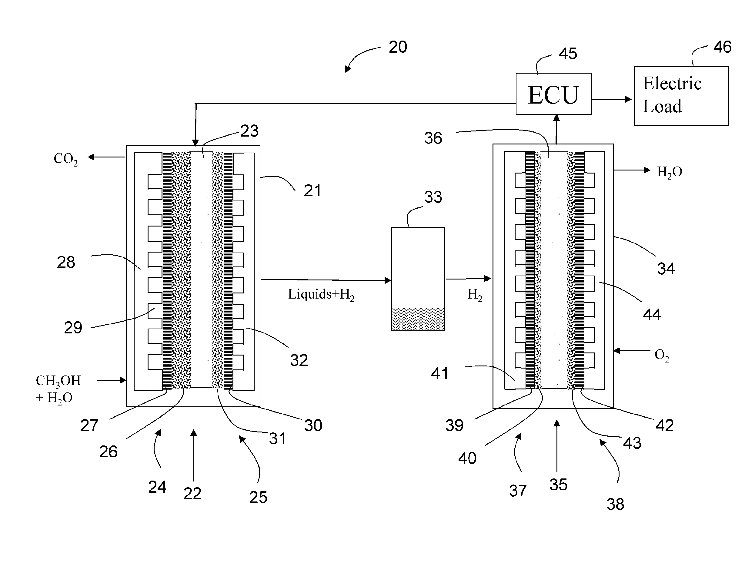
[0168]The performance at temperature 77° C. is calculated. The data for the performance of the DMFC are taken from the reference cited above. The electrolyzer data are taken from our measurements which are shown in FIG. 22. The 1 cm2 area of the MEA 22 of the electrolyzer 21 at 77° C. with 4.2 mg / cm2 PtRu results in a current density of 343 mA / cm2 at 0.4 V. Then H2 corresponding to this current is fed to the fuel cell 34. Taking the data from FIG. 23, a 2.3 cm2 area of the MEA 35 is required, when the fuel cell 34 operates at 0.8 V. If the fuel cell voltage is at 0.8 V a voltage amounting to 0.5 V can be applied to the external load 46. Since 1 cm2 of the MEA 22 the electrolyzer will result in a current of 343 mA and since the external load is supplied with a voltage of 0.4 V the total power supplied to the external load 46 is 137 mW.

[0169]Then the area and catalyst loading needed for same power is calculated for the DMFC. A DMFC operating at 77° C., with ambient pressure cathode, h...


PUM

PropertyMeasurementUnit
operational temperaturesaaaaaaaaaa
temperatureaaaaaaaaaa

Abstract

A system for generating electrical energy comprises an electrochemical reformer for converting fuel into a fuel gas. The fuel gas is supplied to a separator, which removes fuel components from the gas flow to a generator, which uses the fuel gas for generating electrical energy. Electrical power needed for the operation of the reformer is supplied by the generator. An external electric load can also be supplied with electrical energy.

Description

CROSS-REFERENCE TO RELATED APPLICATIONS[0001]The present application is a continuation of pending International patent application PCT / EP2008 / 055076 filed on Apr. 25, 2008, which designates the United States and claims priority of European patent application No. 07 008 545.1 filed on Apr. 26, 2007 and the priority of European patent application No. 07 117 793.5 filed on Oct. 2, 2007. The disclosure of these applications is hereby incorporated by reference in its entirety as part of the present disclosure.FIELD OF THE INVENTION[0002]The invention relates to a system for generating electrical energy comprising:[0003]a fuel reservoir for storage of an organic fuel;[0004]an electrochemical reformer provided with electrical current terminals and arranged for converting the fuel from the fuel reservoir into fuel gas provided at a fuel gas outlet of the reformer;[0005]an electrochemical generator having a fuel gas inlet connected to the fuel gas outlet of the reformer comprising electrical...

Claims


Application Information

Patent Timeline
Patent Type & Authority Applications(United States)
IPC IPC(8): H01M8/06C25B9/23
CPCC25B1/02Y02E60/528H01M8/186H01M8/0656Y02E60/50
Inventor RAO, VINEETSCHREIER, SIEGFRIED
Owner RAO VINEET
Why Eureka
Try Eureka