Liquid crystal display device, liquid crystal display device drive method, and television receiver

a technology of liquid crystal display device and drive method, which is applied in the direction of electric digital data processing, instruments, computing, etc., can solve the problems of increasing power consumption, affecting the viewing angle, and affecting the display effect, so as to prevent the difference in luminance and prevent the effect of display unevenness

Inactive Publication Date: 2010-05-13
SHARP KK
View PDF22 Cites 37 Cited by
  • Summary
  • Abstract
  • Description
  • Claims
  • Application Information

AI Technical Summary

Benefits of technology

[0094]With the arrangement, deviation in time required for steep rise/fall of a voltage applied on a pixel electrode due to a change in H and L levels of a retention capacitor signal in a retention capacitor line is prevented regardless of the number of driving frequencies and the number of scanning lines. This

Problems solved by technology

Although display quality of a liquid crystal display device has been improved, there appears a new problem of viewing angle dependency: a problem of difference in gamma characteristic when seen from a front and gamma characteristic when seen from a skew direction, i.e. a problem of viewing angle dependency in gamma characteristic.
This is problematic particularly when displaying an image such as photograph and when displaying television broadcasting etc.
On the other hand, it is more difficult to produce a liquid crystal panel of the IPS mode with high contrast ratio when seen from the front than to produce a liquid crystal panel of the MVA mode with high contrast ratio when seen from the front.
This raises a problem such as difficulty in preparation of a circuit for generating an oscillating voltage, an increase in power consumption, greater influence of rounding of a waveform due to electric load impedance of a CS bus line.
If a current voltage continu

Method used


Image

  • Liquid crystal display device, liquid crystal display device drive method, and television receiver
  • Liquid crystal display device, liquid crystal display device drive method, and television receiver
  • Liquid crystal display device, liquid crystal display device drive method, and television receiver

Examples


embodiment 1

[0218]One embodiment of the present invention is described below with reference to the attached drawings.

[0219](Structure of Liquid Crystal Display Device)

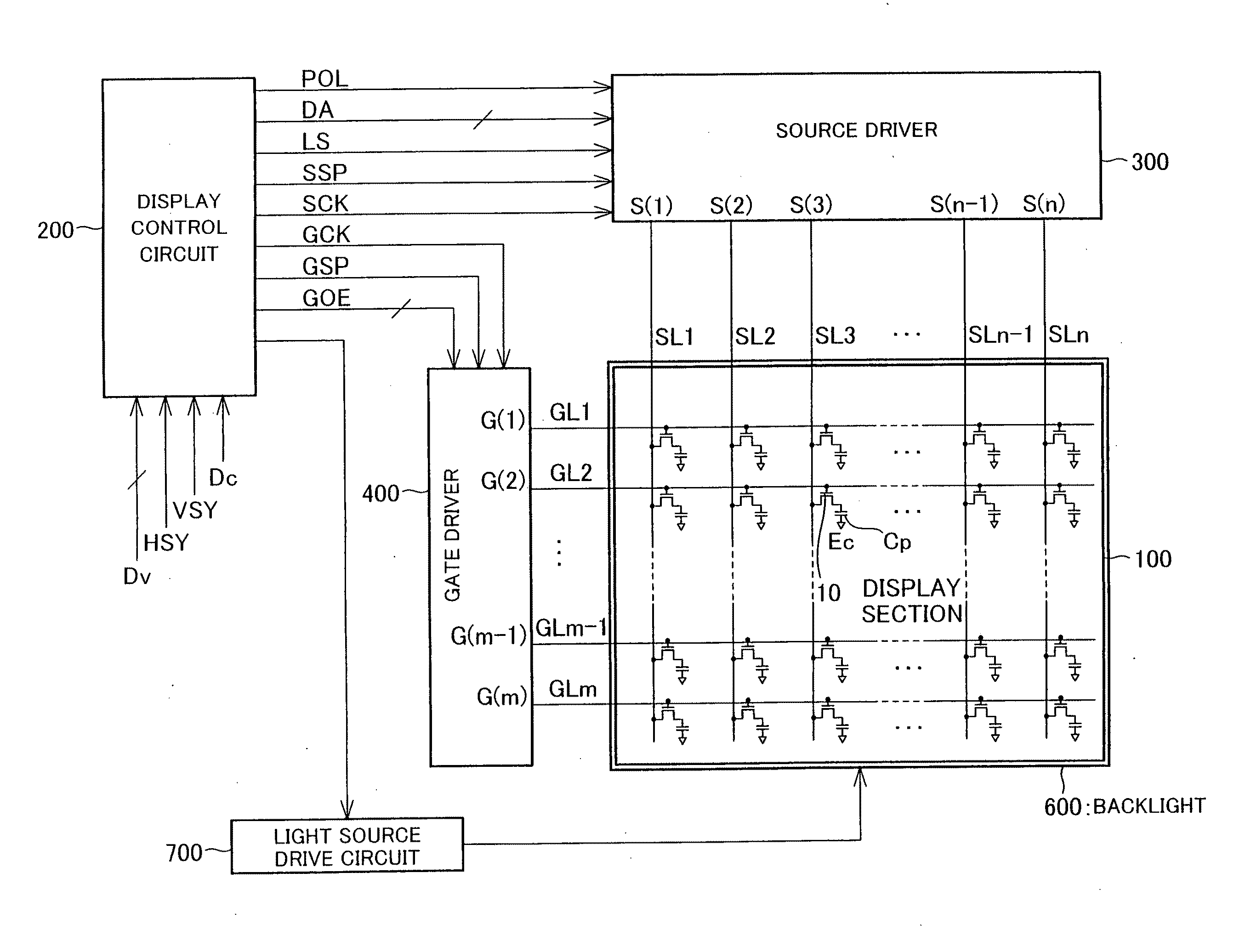
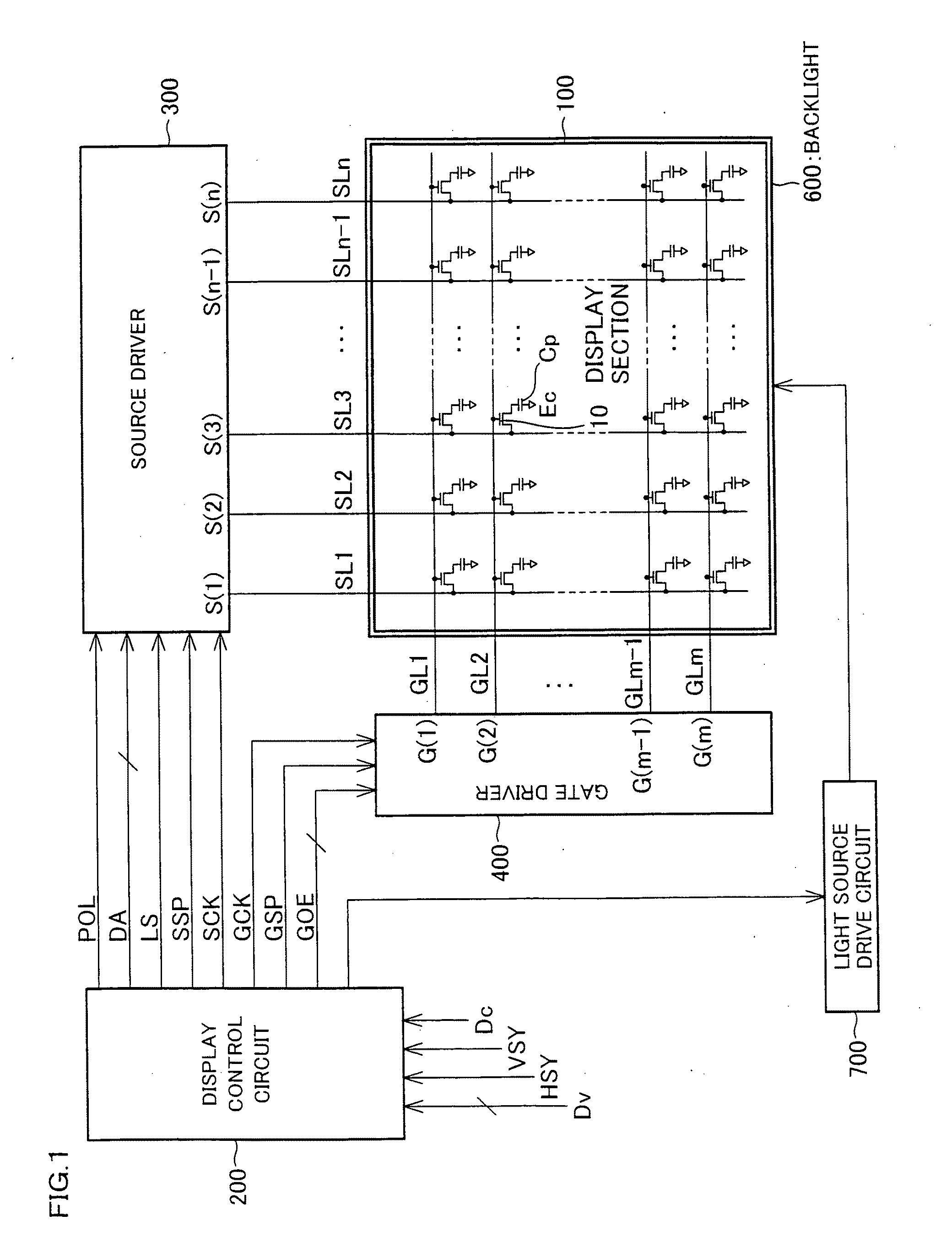
[0220]FIG. 1 is a block diagram showing a structure of a liquid crystal display device of the present invention and an equivalent circuit of a display section of the liquid crystal display device. The liquid crystal display device includes a source driver 300 serving as a data signal line drive circuit, a display section 100 that is an active matrix display section, a backlight 600 serving as a planer illuminating device, a light source drive circuit 700 for driving the backlight 600, and a display control circuit 200 for controlling the source driver 300, the gate driver 400, and the light source drive circuit 700. In the present embodiment, the display section 100 is an active matrix liquid crystal panel. Alternatively, the display section 100 may be integrated with the source driver 300 and the gate driver 400 to form a liquid ...

embodiment 2

[0291]Another embodiment of the present invention is described below with reference to the drawings. Configurations having the same functions as those in Embodiment 1 are given the same reference numerals and explanations thereof are omitted here.

[0292](Configuration of Liquid Crystal Display Device)

[0293]FIG. 15 is a block diagram illustrating a configuration of a liquid crystal display device of the present embodiment and an equivalent circuit of a display section of the liquid crystal display device. The liquid crystal display device is obtained by arranging the liquid crystal display device of FIG. 1 so as to further include a CS control circuit (retention capacitor signal drive section) 90 serving as an auxiliary capacitor line drive circuit. Except for the CS control circuit 90, the liquid crystal display device of the present embodiment is the same as the liquid crystal display device of Embodiment 1 and therefore explanation thereof is omitted here.

[0294]The CS control circu...


PUM


Abstract

In one embodiment of the present invention, a gate driver creates a dummy insertion period in which the driver does not apply a gate on pulse to a scanning signal line immediately after the time of the inversion of a data signal. When a period from the time of the application of the gate on pulse to an odd numbered or even numbered scanning signal line to which the gate on pulse is applied previously to the time of the application of the gate on pulse to an even numbered or odd numbered scanning signal line to which the gate on pulse is applied later is set as an adjacent line writing time lag period for two scanning signal lines adjacent to each other, a CS control circuit allows the polarity of every CS signal to be reversed on the same cycle at least in the adjacent line writing time lag period. This makes it possible to provide a liquid crystal display device capable of offering high quality display in which unevenness in the display is suppressed without being affected by the blunt waveform of the data signal and the blunt waveform of a retention volume signal at the time of the inversion.

Description

TECHNICAL FIELD[0001]The present invention relates to a liquid crystal display device for displaying an image by applying a voltage to liquid crystal, a method for driving the liquid crystal display device, and a television receiver.BACKGROUND ART[0002]A liquid crystal display device is a flat display device having excellent properties such as high definition, a flat shape, light weight, and low power consumption. Recently, due to an increase in display ability, an increase in production ability, and an increase in price competitiveness against other display devices, the market of the liquid crystal display device has spread rapidly.[0003]An in-plane switching mode (IPS mode, see Patent Literature 1) and a multi-domain vertical aligned mode (MVA mode, see Patent Literature 2) in particular are applied to liquid crystal televisions as a liquid crystal display device of a wide viewing angle which is free from a problem such as a great decrease in a display contrast ratio and inversion...

Claims


Application Information

Patent Timeline
IPC IPC(8): G09G3/36G06F3/038
CPCG09G3/3614G09G3/3611G09G3/3655G09G3/3677G09G2300/0443G09G2300/0876G09G2310/0205G09G2310/0224G09G2310/0248G09G2310/0251G09G2310/08G09G2320/0233G09G2320/0261G09G2320/028G09G3/3648
Inventor KITAYAMA, MASAEIRIE, KENTAROSHIMOSHIKIRYOH, FUMIKAZUTSUBATA, TOSHIHIDEYAMADA, NAOSHI
Owner SHARP KK
Why Eureka
Try Eureka