
Ceramic sheet and method for producing the same

a ceramic sheet and ceramic technology, applied in the field of ceramic sheets, can solve the problems of requiring a large amount of energy, cumbersome process, long firing time, etc., and achieve the effects of reducing energy consumption during production, increasing density, and further enhancing crystallographic orientation

Inactive Publication Date: 2010-05-13
NGK INSULATORS LTD
View PDF24 Cites 20 Cited by
  • Summary
  • Abstract
  • Description
  • Claims
  • Application Information

AI Technical Summary

Benefits of technology

[0009]However, in the piezoelectric ceramic described in each of Patent Documents 1 and 2, when the intended piezoelectric material is made flat, firing is performed for two hours under coexistence of a material having the same composition as the piezoelectric material, the process is cumbersome, and the firing time is long, requiring a large amount of energy. Furthermore, in each of Patent Documents 3 and 4, the template material is formed by firing for as long a time as possible (e.g., 5 hours), and a larger amount of firing energy is required to enhance the degree of orientation, thus decreasing production efficiency. Furthermore, in each of Patent Documents 3 and 4, since the template material is subjected to firing for a long period of time, pore growth is promoted, resulting in a decrease in the density of the material.
[0010]The present invention has been achieved in view of the problems described above, and it is a main object of the invention to provide a ceramic sheet in which energy consumption during the production can be further reduced, the density can be increased, and the degree of crystallographic orientation can be further enhanced, and a method for producing the ceramic sheet.
[0011]In order to achieve the above-mentioned object, the present inventors have made an attempt in which inorganic particles including, as a main component, an oxide represented by general formula ABO3 and containing a volatile component are mixed such that the A / B ratio is 1.05 or more, the inorganic particles are formed into a self-supported planar shaped body with a thickness of 30 μl or less, and the shaped body is fired, without an inactive layer or with an inactive layer which does not substantially react with the shaped body and is disposed adjacent to the shaped body, at a temperature-rising rate of 30° C. / minor more in a temperature range which is equal to or higher than a temperature at which the volatile component volatilizes. As a result, it has been found that energy consumption during the production can be further reduced, the density can be increased, and the degree of orientation of crystals contained in the sheet can be further increased, and thus the present invention has been completed.
[0014]In the method for producing a ceramic sheet according to the present invention, energy consumption during the production can be further reduced, the density can be increased, and the degree of crystallographic orientation can be further enhanced. The reason for such effects is not clear, but can be presumed as follows. For example, since the planar shaped body with a thickness of 30 μm or less is fired, crystal grain growth easily occurs in the surface direction of the sheet, and the degree of orientation can be further enhanced. Furthermore, in the oxide represented by general formula ABO3, the element in the A site, which is generally volatile, is believed to function as a flux that activates the movement of atoms on the surface of the grains, and by mixing a large amount of the element in the A site during the raw material synthesis step and by increasing the temperature-rising rate (to 30° C. / min or more), grain growth can rapidly proceed while the excess amount of the element in the A site is volatilized at a higher temperature. Thus, the orientation is believed to be further enhanced in a short period of time. Consequently, since the total firing time can be shortened, energy consumption during the production can be further reduced, pore growth, which may be caused by firing for a long period of time, can be more suppressed, and the density can be further prevented from decreasing. Furthermore, in the ceramic sheet produced by this production method, the number of crystal grains present in the thickness direction of the sheet at any one point is substantially one, a surface of the sheet including a specific crystal plane of the crystal grains, the sheet has a high density of 85% or more, the density being defined as the ratio of the area of the crystal grains to the total area, and the degree of orientation of the sheet measured by the Lotgering method is high at 40% or more.
[0015]Furthermore, in the oxide represented by general formula ABO3, the element in the A site added in excess provides, in addition to a function of compensating for the volatile component, an effect of promoting grain growth (orientation). Therefore, it is presumed that, by increasing the temperature rapidly, a dense, oriented sheet can be obtained for a short period of time. In this regard, in a material other than the material represented by general formula ABO3, it is expected that the same effect can be obtained if a grain growth (orientation) promoter is added and the temperature is increased rapidly. As the grain growth promoter, as in the element in the A site added to general formula ABO3, a material or a material composed of a constituent element which has a low melting point and which is volatile is suitable because the properties are not adversely affected.

Problems solved by technology

However, in the piezoelectric ceramic described in each of Patent Documents 1 and 2, when the intended piezoelectric material is made flat, firing is performed for two hours under coexistence of a material having the same composition as the piezoelectric material, the process is cumbersome, and the firing time is long, requiring a large amount of energy.
Furthermore, in each of Patent Documents 3 and 4, the template material is formed by firing for as long a time as possible (e.g., 5 hours), and a larger amount of firing energy is required to enhance the degree of orientation, thus decreasing production efficiency.

Method used


Image

  • Ceramic sheet and method for producing the same
  • Ceramic sheet and method for producing the same
  • Ceramic sheet and method for producing the same

Examples


examples

[0046]Experimental examples in which ceramic sheets are specifically produced will be described below.

[0047](Synthesis Step of Synthesizing Inorganic Particles)

[0048]Powders (Li2CO3, Na2CO3, K2CO3, Nb2O5, and Ta2O5) were weighed so as to satisfy the composition {Li0.07(Na0.5K0.5)0.93}A / B [Nb0.9Ta0.1]O3 (A / B=1.00). The weighed powders, zirconia balls, and ethanol as a dispersion medium were placed in a plastic pot, and wet mixing and pulverization were performed using a ball mill for 16 hours. The resulting slurry was dried using an evaporator and a dryer, and then calcination was performed at 850° C. for 5 hours. The calcined powder, zirconia balls, and ethanol as a dispersion medium were subjected to wet pulverization using a ball mill for 40 hours, followed by drying using an evaporator and a dryer. Thereby, powder of inorganic particles composed of {Li0.07(Na0.5K0.5)0.93}A / B [Nb0.9Ta0.1]O3 (A / B=1.00) was obtained. The average particle diameter of the resulting powder was measured...

experimental examples 2 to 8

[0052]A ceramic sheet of Experimental Example 2 was formed as in Experimental Example 1 except that the shaped body was fired in a volatilization-suppressing state in which the volatilization of the volatile component was suppressed. The firing in the volatilization-suppressing state was performed in a state in which green shaped sheets (size: 5 mm×40 mm, thickness: 100 μm) composed of the same shaping raw materials as those for the sheet-like shaped body were placed on the setter, on which the sheet-like shaped body was placed, outside the four sides of the sheet-like shaped body so as to surround the sheet-like shaped body, and a quadrangular plate made of zirconia (size: 70 mm square, height: 5 mm) was further placed thereon. In such a manner, the space around the sheet-like shaped body was minimized, and the same shaping raw materials as those for the sheet-like shaped body were allowed to coexist so that the atmosphere around the sheet-like shaped body was filled with the vapor...

experimental examples 9 to 16

[0053]A ceramic sheet of Experimental Example 9 was formed as in Experimental Example 1 except that, in the raw material synthesis step, the raw materials were mixed such that the A / B ratio was 1.20. Furthermore, a ceramic sheet of Experimental Example 10 was formed as in Experimental Example 9 except that, in the firing step, the shaped body was fired in a volatilization-suppressing state in which the volatilization of the volatile component was suppressed. Furthermore, a ceramic sheet of Experimental Example 11 was formed as in Experimental Example 9 except that, in the firing step, the shaped body was fired in a temperature range of 600° C. (degreasing temperature) or higher, at a temperature-rising rate of 40° C. / min. Furthermore, a ceramic sheet of Experimental Example 12 was formed as in Experimental Example 11 except that, in the firing step, the shaped body was fired in a volatilization-suppressing state in which the volatilization of the volatile component was suppressed. F...


PUM

PropertyMeasurementUnit
thicknessaaaaaaaaaa
thicknessaaaaaaaaaa
temperatureaaaaaaaaaa

Abstract

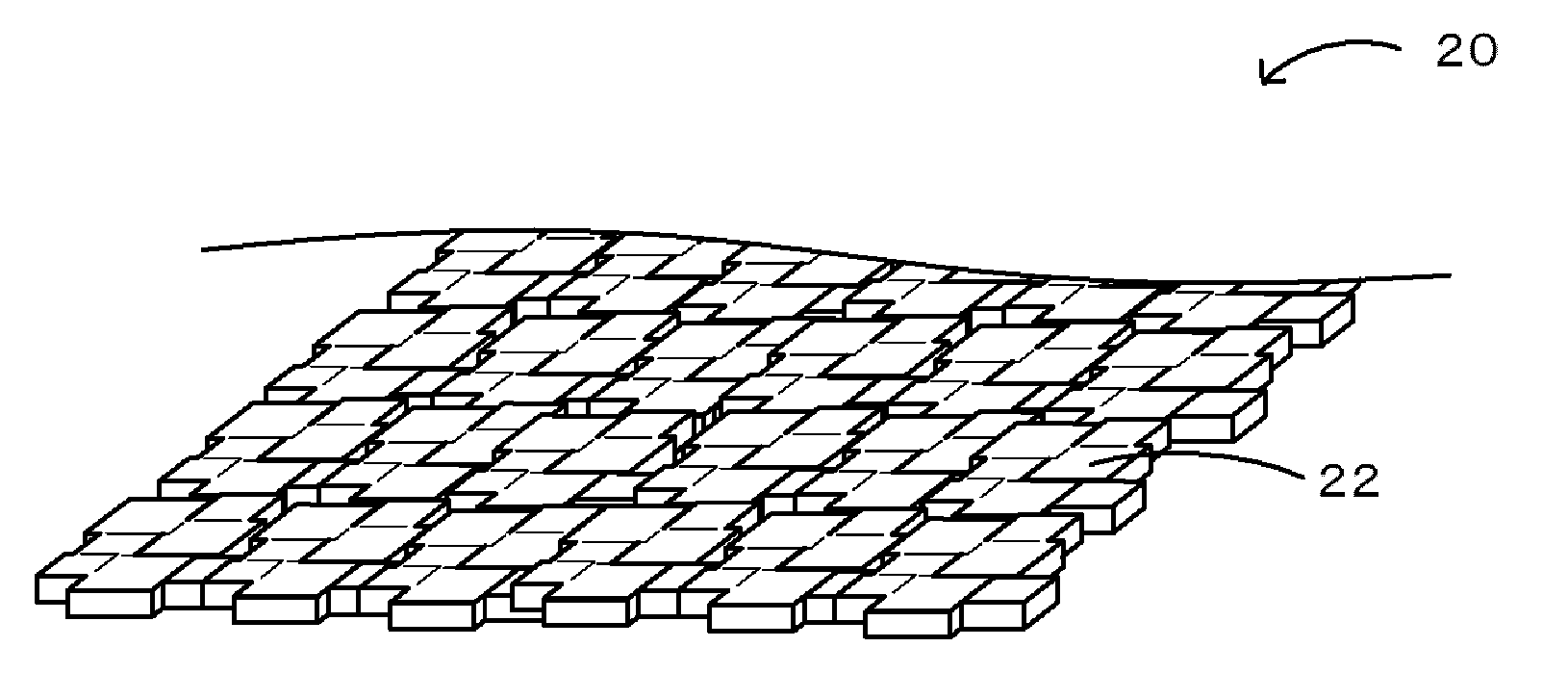
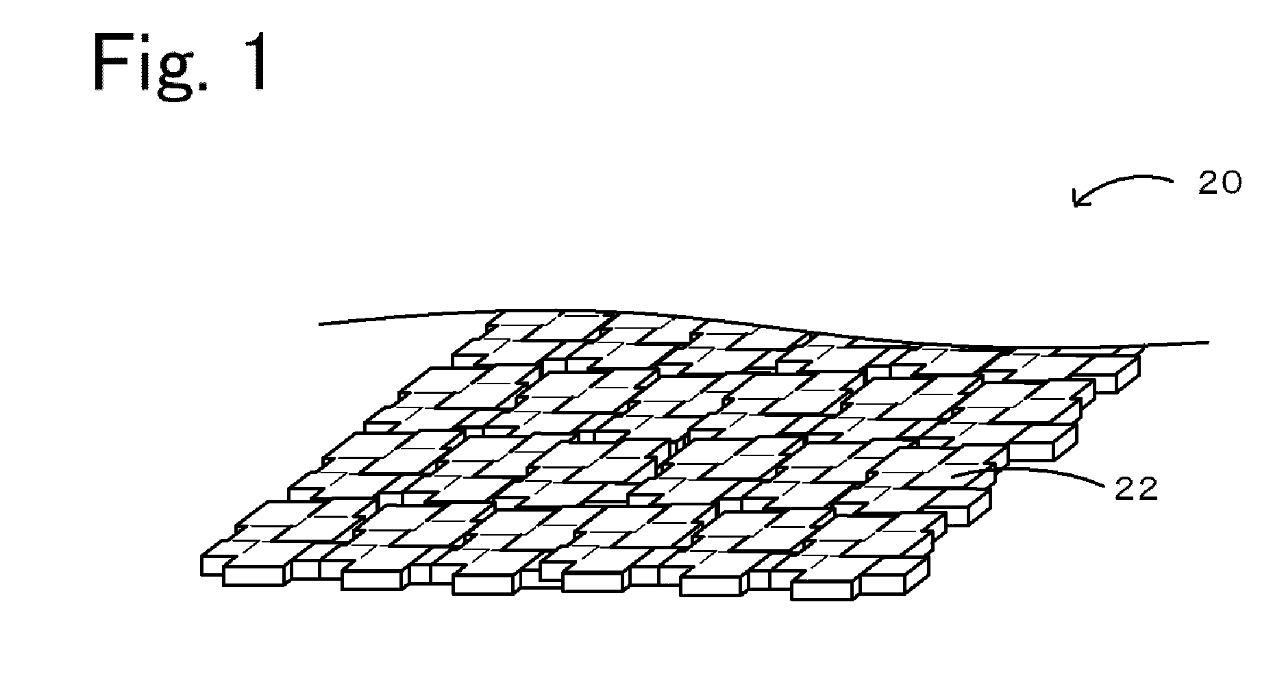
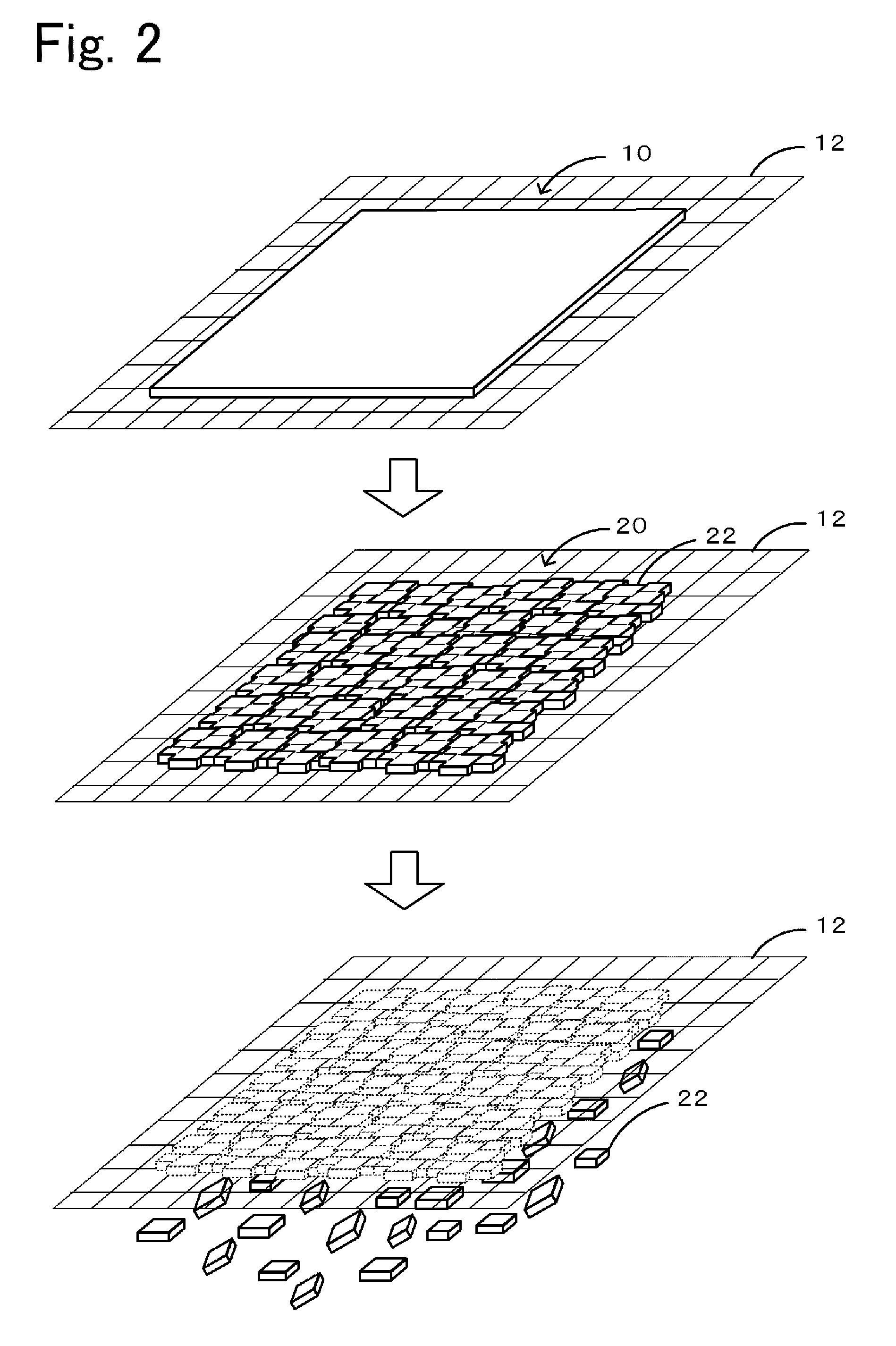
A ceramic sheet 20 is produced by a method in which inorganic particles including, as a main component, an oxide represented by general formula ABO3 and containing a volatile component are mixed such that the A / B ratio is 1.05 or more, the inorganic particles are formed into a self-supported planar shaped body with a thickness of 30 μm or less, and the shaped body is fired, without an inactive layer or with an inactive layer which does not substantially react with the shaped body and is disposed adjacent to the shaped body, at a temperature-rising rate of 30° C. / min or more in a temperature range which is equal to or higher than a temperature at which the volatile component is volatilized.

Description

BACKGROUND OF THE INVENTION[0001]1. Field of the Invention[0002]The present invention relates to ceramic sheets and methods for producing the same. More particularly, the invention relates to piezoelectric / electrostrictive ceramic sheets.[0003]2. Description of the Related Art[0004]To date, piezoelectric ceramics whose properties are improved by aligning the orientations of tabular grains have been proposed. For example, a piezoelectric ceramic having crystal grains whose grain diameters in a width direction are larger than those in a thickness direction when observed in a cross section in the thickness direction has been proposed (refer to Patent Documents 1 and 2). Furthermore, piezoelectric ceramics whose piezoelectric properties are further improved by increasing the degree of orientation of a specific crystal plane in the crystals have been proposed. For example, a piezoelectric ceramic has been proposed, which is produced by forming a template material, whose grains are tabula...

Claims


Application Information

Patent Timeline
Patent Type & Authority Applications(United States)
IPC IPC(8): B32B5/00C04B35/64C04B35/622H01L41/187H01L41/22H01L41/39H01L41/43
CPCC04B35/475H01L41/1873C04B35/62218C04B2235/3201C04B2235/3203C04B2235/3255C04B2235/3291C04B2235/3298C04B2235/5445C04B2235/6025C04B2235/6562C04B2235/6587C04B2235/77C04B2235/787C04B2235/79C04B2235/9623H01L41/43C04B35/495H10N30/8542H10N30/097
Inventor YOKOYAMA, SHOHEIKOBAYASHI, NOBUYUKINANATAKI, TSUTOMU
Owner NGK INSULATORS LTD
Learn More