Multi-Channel Receiver Architecture and Reception Method

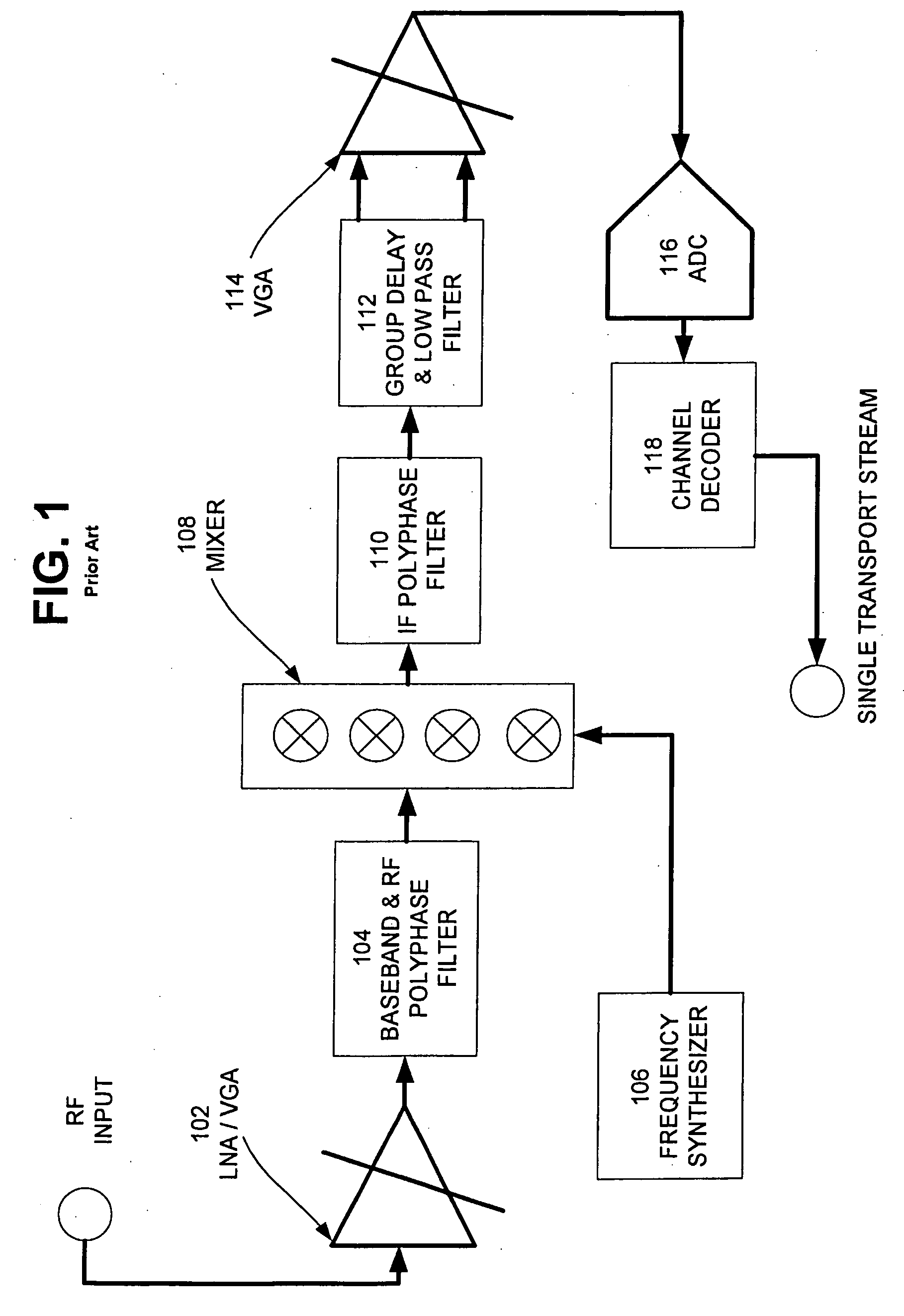
a multi-channel receiver and receiver technology, applied in the field of multi-channel receiver architecture and reception method, can solve the problems of limiting the integration of the tuner into a larger soc system, the existing receiver architecture based on the concept shown in fig. 1 is not able to meet properly the need for multi-channel reception, and the complexity of the system implementation, signal quality, cost effectiveness,

Active Publication Date: 2010-05-13
NXP BV
View PDF14 Cites 33 Cited by
  • Summary
  • Abstract
  • Description
  • Claims
  • Application Information

AI Technical Summary

Benefits of technology

[0108]In another embodiment, the signal information contained in the multiple signals are used to affect the front-end (pre-processor and ADC) parameters such that the reception is optimal.

Problems solved by technology

In most cases, the tuner is realized in a Silicon Bipolar or BiCMOS process in order to reach the RF performance required, but which restricts the tuner from being integrated into a larger SoC system.
Existing receiver architectures based on the concept shown in FIG. 1 are not able to satisfy properly the need for multi-channel reception.
This approach, however, faces major limitations related to complexity of system implementation, signal quality, and cost effectiveness.
As the number of simultaneously required streams / channels goes beyond two, the conventional approach becomes completely impractical.
However, every time the RF input signal is replicated its quality degrades significantly with no possibility to recover the quality back.
Such an approach is clearly impractical.
Conventional I / Q receiver architectures are significantly affected by the well-known image rejection problem rising from mismatches in I and Q paths and their associated mixers.
Further implementation limitations in I / Q mixers are also characteristics of this approach.
The block tuner described above enables DOCSIS 3.0, but does not enable unrestricted multi-channel functionality.
Several implementation limitations appear as well.
The block receiver approach is clearly not the best for interference reasons.
A second major issue is the capability to process digital signals with very high data rates.
The steepness of the digital filters required in order to isolate one 6 MHz channel out of 100 TV channels in the 1 GHz band at the aforementioned rate complicates the situation significantly.
Conventional digital signal processing selectivity techniques are not able to deal with these issues with area and power efficiency at reasonable levels for commercial use.
The development of discrete high-speed ADC chips and discrete multi-channel selection filtering chips does not solve the overarching problem of managing timing issues resulting from the high sample rates required for a multi-channel receiver.
Data transportation at these speeds is extremely difficult, especially when it comes to transport from one IC to another.
In addition, transporting data at such rates from one IC to another requires awareness of electromagnetic compatibility (EMC) and related interference issues that can easily impair the ADC performance.
The input signal of the ADC is practically the input of the receiver, therefore very weak and easily susceptible to signal degradation.
Use of low swing differential signaling standards (e.g. LVDS) could reduce EMC relate issues, but not to an acceptable level due to the extreme high data rate (thus, very high number of high speed signals) to convey the real data stream of 20-80 Gbits / sec from IC to IC.
Additionally, while it might seem feasible to use on-chip memory to alleviate the EMC related issues of high-speed IC-to-IC transmission, memory usage raises technical issues of its own and is not feasible in applications where real time streaming is desired.
In both cases, the complexity is significantly higher because the circuits that must be synchronized may be 1-10 cm's apart.

Method used


Image

  • Multi-Channel Receiver Architecture and Reception Method
  • Multi-Channel Receiver Architecture and Reception Method
  • Multi-Channel Receiver Architecture and Reception Method

Examples


Embodiment Construction

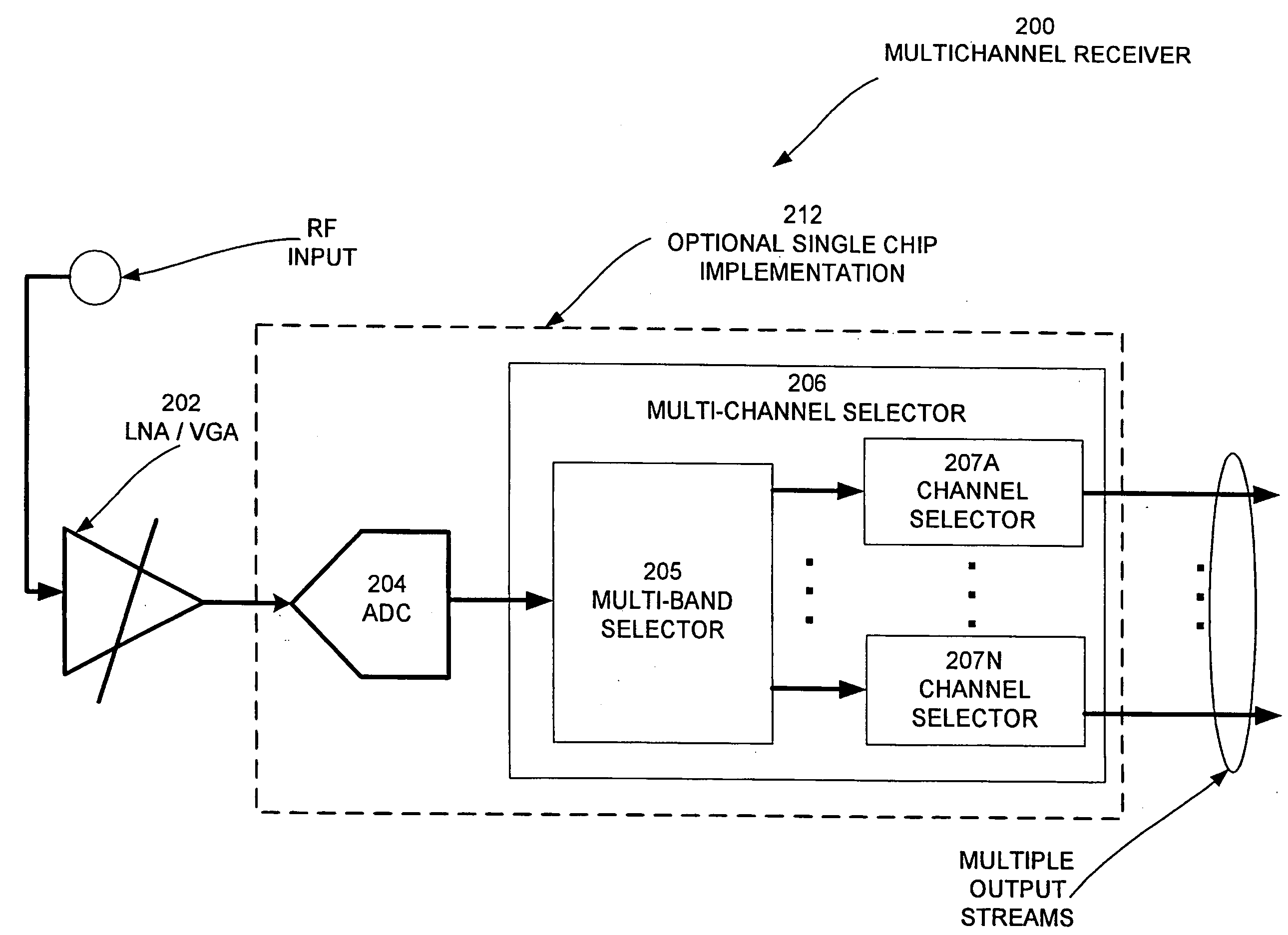
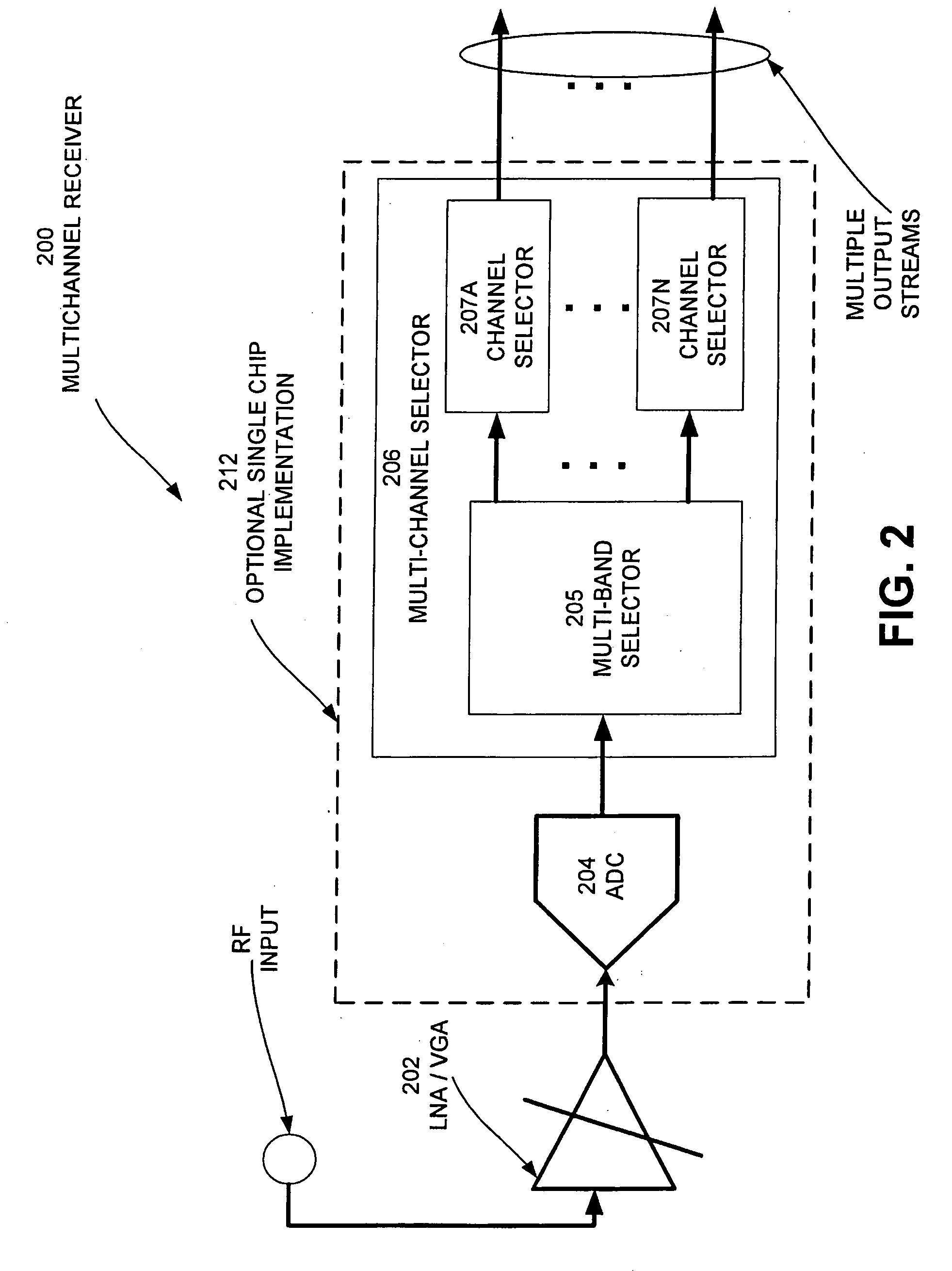
[0042]In an embodiment, a multi-channel receiver uses an analog to digital converter (ADC) and a high speed multi-band selector (MBS) to provide a selectable multi-channel output to an external device. In another embodiment the ADC and the MBS are implemented on a single IC. In this embodiment, data are transported at very small distances on-chip in a synchronized manner. The IC receiver outputs only the preselected channel information at a significantly lower data rate (e.g. 10MSample / sec instead of 2 GSample / sec) thereby mitigating electromagnetic compatibility (EMC) issues. FIG. 2 illustrates the logical components of a multi-channel receiver (MCR) according to an embodiment.

[0043]MCR 200 comprises LNA / VGA 202, ADC 204, and multi-channel selector 206. Multi-channel selector 206 comprises multi-band selector 205 and channel selectors 207A-207N. Depending on the number of channel selectors that are implemented in multi-channel selector 206 will determine the number of output stream...


PUM


Abstract

A multi-channel receiver comprising an ADC and a multi-band, multi-channel selector. The ADC converts a broad-band multi-channel signal into a digital signal. The digital signal is then broken into sub-bands each containing a plurality of channels. A channel selector selects desired channels from the appropriate sub-band. The multi-channel receiver may deliver simultaneous channels equal to the number of channel selectors that have been implemented. The multi-channel receiver may be implemented on a single integrated circuit.

Description

BACKGROUND AND SUMMARY[0001]Current television receivers receive a single channel through a single tuner. The evolving market for data and programming services will demand that receivers have the capability of multi-channel tuning.[0002]A block diagram of a conventional single-channel cable TV receiver is illustrated in FIG. 1. The composite TV signal is received at the input of the receiver and amplified to the correct level with a low-noise-amplifier and variable gain amplifier (LNA / VGA) 102. A programmable band selection filter 104 can potentially make a pre-selection on the composite signal to limit its bandwidth and easy the subsequent signal processing operations.[0003]A specific TV channel is selected with the use of a frequency synthesizer 106 that tunes to the corresponding channel frequency. By multiplying the synthesized frequency reference signal and the received signal together with the aid of the mixer circuit 108, the wanted channel is down-converted (its carrier freq...

Claims


Application Information

Patent Timeline
Patent Type & Authority Applications(United States)
IPC IPC(8): H04B1/18H04N5/50
CPCH03H17/06H04B1/0025H04B1/001H03H2218/08
Inventor KONSTANTINOS, DORISJANSSEN, ERWIN
Owner NXP BV
Why Eureka
Try Eureka