Devices, Systems and Methods for Modular Payload Integration for Unmanned Aerial Vehicles

a technology of modular payload and unmanned aerial vehicles, which is applied in the field of wing designs with integrated aerodynamic payload integration systems for unmanned aerial vehicles (uavs), can solve the problems of reducing the efficiency of uavs, so as to reduce the thickness of airfoil and minimize efficiency loss

Inactive Publication Date: 2010-05-20
MAV6 LLC
View PDF8 Cites 35 Cited by
  • Summary
  • Abstract
  • Description
  • Claims
  • Application Information

AI Technical Summary

Benefits of technology

[0018]In a further exemplary embodiment, the present invention is a method for adding a payload system to a UAV. The method includes creating a rigid shell to complement an airfoil of a wing while increasing a thickness of the airfoil, attaching the rigid shell to a center wing of the UAV wherein a payload cavity is created bound by the wing and the rigid shell, and attaching the center wing to the UAV. The rigid shell is aerodynamically shaped to minimize efficiency loss.

Problems solved by technology

Though conventional UAVs have been highly successful in gathering video or footage of the terrain and personnel within hostile territory, the gathering of other types of data has been a more difficult undertaking.
Part of the reason for such difficulty is that UAVs are generally very light, some on the order of 5-10 pounds, and the installation of heavy equipment or other bulky payloads completely distorts the flying and maneuvering abilities of such aerial vehicles.
Either way requires a very manual process, and the end result is not rugged.
Furthermore, an inordinate amount of man hours are spent guessing as items are placed wherever they can fit on the center wing section with no protection against failures, center of gravity effects, or drag.
Not surprisingly, these types of payload attachments have caused many problems.
For example, with the duct-taped payload, the RAVEN only reliably flies about 45 minutes or around three-quarters of its normal flight time due to degraded aerodynamics (increased drag), and increased weight.
Thus, there have been different configurations attempted, but each has resulted in a significant drop in the flight time.
Some of the lost flight time comes from a heavier payload forcing the motor to work harder to get the RAVEN up to altitude and constantly re-climbing, because every plane has a glide ratio.
Also, because the center of balance of the RAVEN changes along with the drag, the RAVEN with the payload could porpoise, affecting the ability to keep a camera focal point on target.
Furthermore, the takeoff of the RAVEN is significantly affected.
While testing did not produce stall outs, many of the takeoffs do not perform in a normally observed manner, presumably all due to the weight increase.
This is a significant problem in some of the overseas areas in which the RAVEN is used because of high temperatures.
The additional drag and extra weight of the payload on the RAVEN without having some kind of lift characteristics due to the packaging causes improper or failed takeoffs.

Method used


Image

  • Devices, Systems and Methods for Modular Payload Integration for Unmanned Aerial Vehicles
  • Devices, Systems and Methods for Modular Payload Integration for Unmanned Aerial Vehicles
  • Devices, Systems and Methods for Modular Payload Integration for Unmanned Aerial Vehicles

Examples


Embodiment Construction

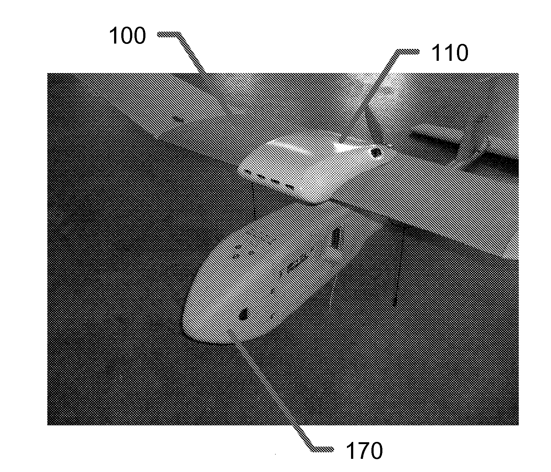
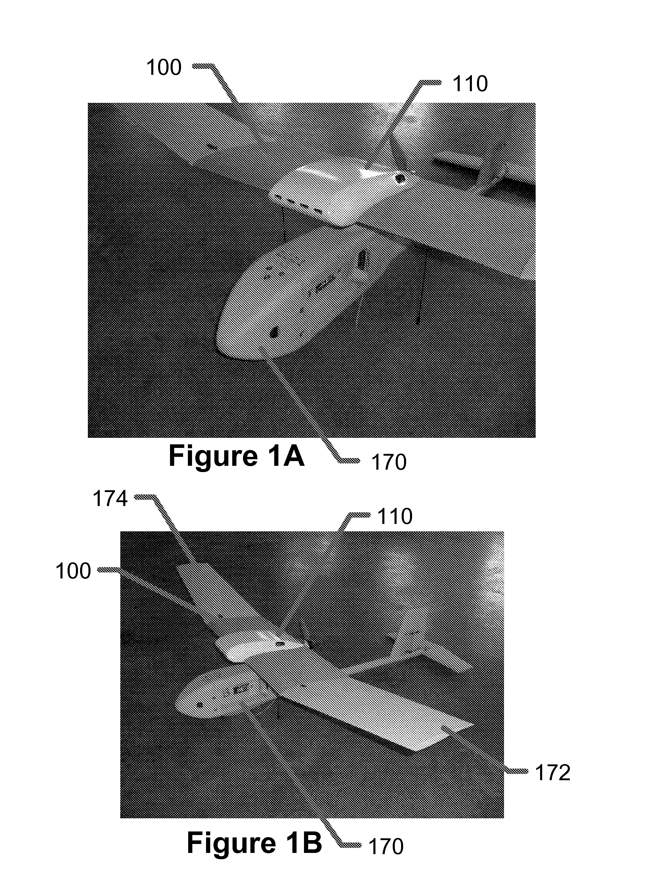
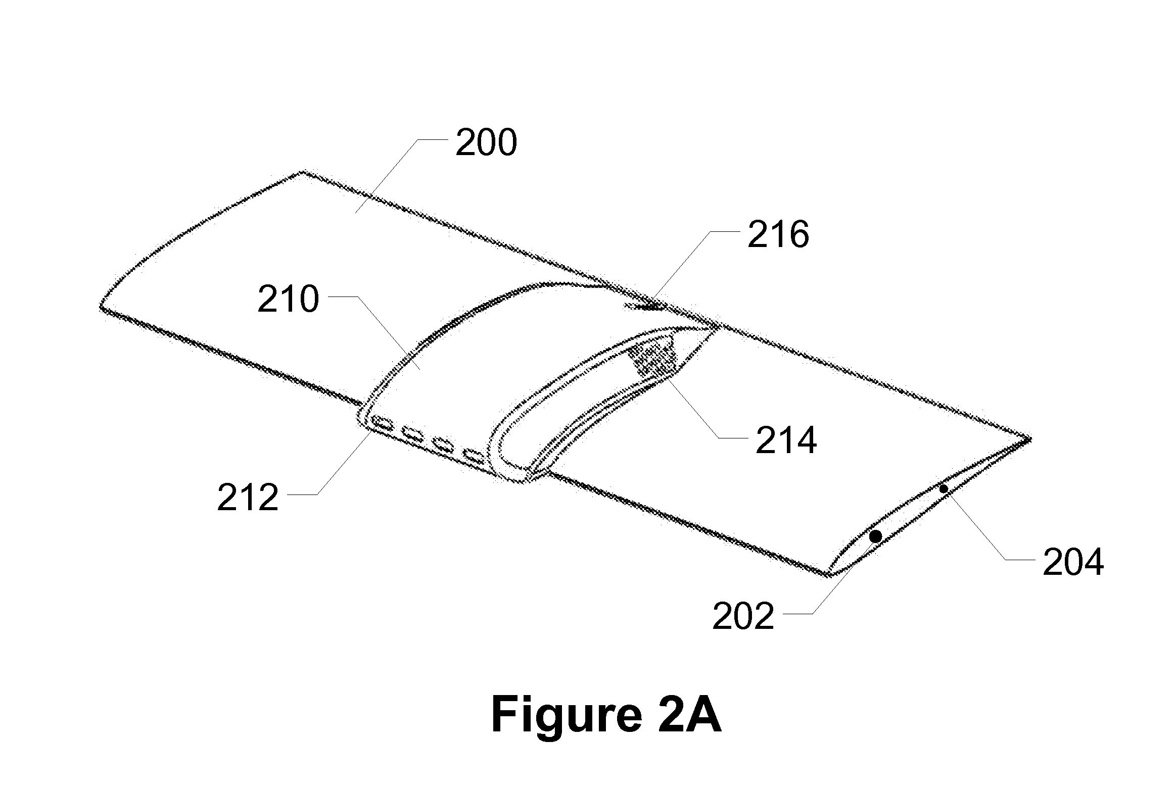
[0040]The present invention provides systems and methods of providing wing design and flexible payload integration capabilities on existing modularly assembled UAVs. In exemplary embodiments of the present invention a payload cavity is built into a wing of a UAV. The payload cavity comprises a smaller cavity carved out of the wing joined by an optionally larger cavity created by a rigid cover or shell that is coupled with the wing. The rigid cover is shaped such that the union of the cover and wing forms a new airfoil with an increased payload cavity thickness while maintaining aerodynamic quality. The payload cavity can be used to store small electronics such as single-board computers, GPS receivers, extra batteries for longer UAV flights, explosives for offensive UAVs, and other payloads that fit within the cavity footprint and electrical power capabilities. The rigid cover is easily removed to expose the payload cavity so its contents can be removed, replaced, etc.

[0041]“Airfoil,...


PUM


Abstract

Devices, systems and methods are disclosed which relate to providing wing designs with payload integration capabilities on existing modularly assembled unmanned aerial vehicles (UAVs). Exemplary embodiments of the present invention present a novel technique of adding payloads to existing UAVs while improving flight performance over existing techniques by maintaining a similar overall weight with improved aerodynamic properties. The technique includes using a reinforced foam core center wing with a fiberglass epoxy skin. A lightweight payload canopy cover integrates onto the center wing as an agnostic enclosure for payloads. The payload canopy cover may contain venting holes for the cooling of electronic payloads. The systems may also include common devices such as antennas, GPS, and batteries for use with a wide range of payloads.

Description

[0001]This application claims priority to U.S. Provisional Patent Application Ser. No. 61 / 115,933, filed Nov. 18, 2008, and to U.S. Provisional Patent Application Ser. No. 61 / 116,289, filed Nov. 19, 2008, the contents of both of which are hereby incorporated by reference in their entirety into this disclosure.BACKGROUND OF THE INVENTION[0002]1. Field of the Invention[0003]The present invention relates to expanding mission capabilities and payload architecture for UAV system wing designs though the means of an open-architecture payload bay. More specifically, the present invention relates to wing designs with integrated aerodynamic payload integration systems for unmanned aerial vehicles (UAVs).[0004]2. Background of the Invention[0005]Unmanned aerial vehicles (UAVs) are unpiloted aircraft which may be controlled remotely or based upon a pre-programmed flight plan. UAVs have become an increasingly important tool for law enforcement, military, and security personnel to travel and gath...

Claims


Application Information

Patent Timeline
Patent Type & Authority Applications(United States)
IPC IPC(8): B64C1/22G01C21/00
CPCB64C2201/128B64C39/024B33Y80/00B64U2101/60
Inventor BALLARD, BRIAN ADAMSKLUESENER, ROBERT DANIELWOWCZUK, ZENOVY STEPHANWATSON, ALEXANDER COBB
Owner MAV6 LLC
Why Eureka
Try Eureka