
Mixing apparatus and process

a technology of mixing apparatus and process, which is applied in the direction of mixing, chemical/physical/physicochemical processes, transportation and packaging, etc., can solve the problems of affecting the progress of the transportation of the mixture, affecting the production and maintenance of the mixture, and affecting the quality of the mixture, so as to achieve the effect of efficient dispersion of the substance flowing in the vessel, reducing the difficulty of mixing, and ensuring the consistency of the mixing

Active Publication Date: 2010-05-20
NITECH SOLUTIONS LTD
View PDF19 Cites 13 Cited by
  • Summary
  • Abstract
  • Description
  • Claims
  • Application Information

AI Technical Summary

Benefits of technology

[0014]The spacing of the baffles and the control of the flow rate is effective in producing and maintaining uniform mixing and efficient dispersion of a substance flowing in the vessel. As this mixing is achieved without oscillation, much of the complexity involved in the design of the apparatus and associated plant is removed. In particular, the apparatus of the present invention requires fewer parts than oscillatory apparatus and obviates the considerable technical challenges associated with imparting oscillation to a sealed system. The baffles also aid the formation of turbulent flow at flow rates lower than those necessary when using traditional loop or pipe reactors.
[0041]imparting unidirectional linear motion to the polysaccharide and solvent in the tubular vessel using flow control means;wherein the unidirectional linear motion is imparted using the flow control means to sustain a flow of the polysaccharide and solvent at a sufficient flow rate to produce and maintain a uniformly mixed and efficiently dispersed polysaccharide mixture.

Problems solved by technology

However, the use of such reactors in the transportation of consistently mixed materials has several limitations and drawbacks.
Disrupting the flow introduces an extra element of complexity, and impedes the progress of the transportation of the mixture.
However, the use of oscillatory baffled reactors by necessity requires the introduction of a means for producing oscillations.
This often complicates the design of the equipment, and in turn the design of any plant in which the equipment is to be used.
In particular, there are many technical challenges that must be addressed around the oscillation and sealing arrangement.

Method used


Image

  • Mixing apparatus and process
  • Mixing apparatus and process

Examples


process example 1

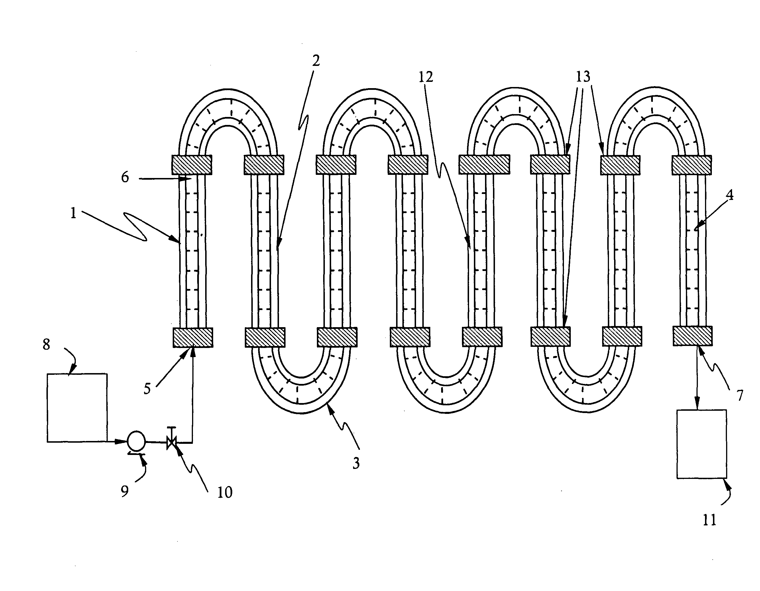
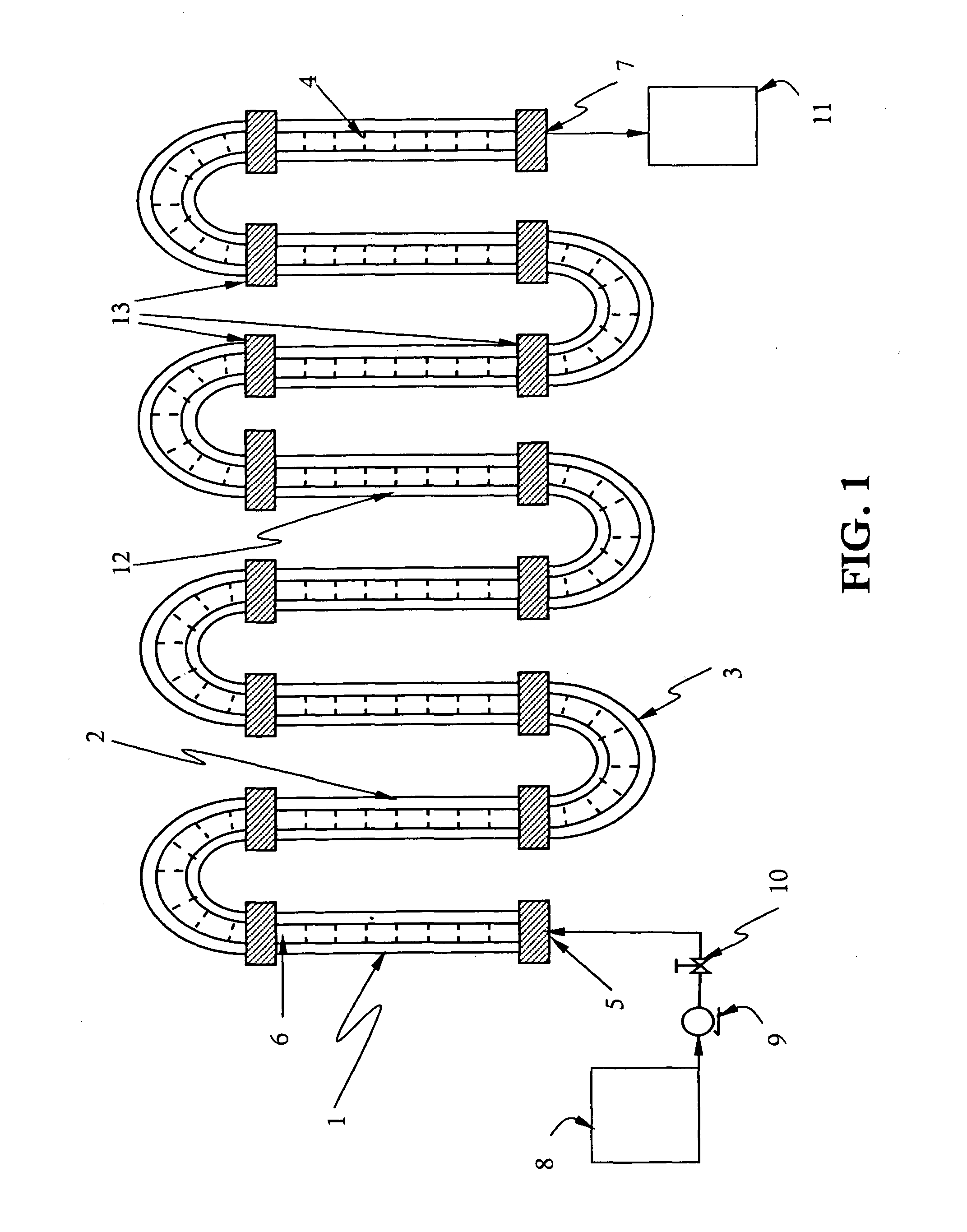
[0047]Use of the system of FIG. 1 will now be described with reference to the transportation of a starch suspension with consistent mixing.

[0048]The feed tank 8 is charged with a starch suspension. The feed tank is then agitated using a set of moving baffles (not shown in FIG. 1) for a certain amount of time and the valve 10 is opened to allow the feed to be added to the tubular vessel 1 to a predetermined level.

[0049]Thereafter, motion is imparted on the contents of the tubular vessel using the pump 9. The pump imparts motion on the constituents in a non-oscillatory fashion. Also, in this example, the pump is adapted to impart a flow rate which gives a Reynolds number greater than 500 to the contents of the tubular vessel, and the flow of the contents or substance in the tubular vessel is laminar flow. The contents are then transported, with the maintenance of consistent mixing, along the length of the tubular vessel. The mixture can be drawn off at a suitable outlet port.

[0050]The...

process example 2

[0052]While the above Example 1 involves a liquid-gas mixture, the tubular baffled vessel 1 is also useful for nitration of toluene, which is a liquid-liquid type reaction. In this operation, the mix of acids (mainly nitric acid and sulphuric acid) is premixed in the feed tank 8 and pumped into the tubular baffled vessel 1 via the metering pump 9 and control valve 10 at a flow rate such that the net flow Reynolds number exceeds 500. The mixed acids are re-circulated while the tubular baffled vessel 1 is heated up to the reaction temperature of 130° C. Once the temperature has been reached, toluene at a given temperature (either at room temperature or pre-heated) is introduced into the vessel 1 at the input point 6. The sufficient flow rate together with the presence of baffle plates ensures most effective dispersion of toluene enabling small and uniform toluene droplets to be formed in the mixed acid stream along the vessel 1. The nitration reaction takes place, and the product of n...

process example 3

[0053]Use of the tubular baffled vessel suitable for solid-liquid processes will now be described with reference to a starch modification process. A slurry of starch-water is pumped into the vessel 1 continuously via the metering pump 9 and the control valve 10 at a given rate so that the net flow Reynolds number is greater than 500. At the same time, the vessel 1 is heated up to a given reaction temperature using the jacket facility 12. When the reaction temperature has been reached, acetic anhydride is added at the input point 6, and the acetylation reaction takes place along the vessel. By controlling the pH along the tubular baffled vessel 1 by addition of base at 13, the product of the modified starch is continuously collected at the product tank 11. In this process, the starch solid particles with solid concentrations up to 55% are uniformly suspended in the liquid phase due to the uniform mixing and near plug flow conditions achieved by combining the flow rate and the baffle ...


PUM

PropertyMeasurementUnit
Timeaaaaaaaaaa
Timeaaaaaaaaaa
Pressureaaaaaaaaaa

Abstract

A continuous, semi-continuous or fed-batch mixing apparatus and process for producing and maintaining a consistently mixed substance uses a tubular vessel equipped with a plurality of annular baffles configured to initiate and maintain uniform mixing and efficient dispersion of the substance in the tubular vessel, with a pump to impart unidirectional linear and non-oscillatory motion to the substance in the tubular vessel thereby promoting and maintaining uniform mixing and efficient dispersion of the substance.

Description

TECHNICAL FIELD[0001]The present invention relates to an improved mixing apparatus and process for maintaining consistently mixed materials. In particular, the present invention relates to an improved apparatus and method for the transportation of suspensions and dispersions incorporating solids, liquids and / or gases with consistent mixing.BACKGROUND ART[0002]Existing technologies for transporting and mixing materials include tubular, loop or pipe reactors (such as the BHR Group Limited Flex-Reactor). However, the use of such reactors in the transportation of consistently mixed materials has several limitations and drawbacks. In particular, some form of disruption to the flow is often used to ensure that effective mixing is maintained. Disrupting the flow introduces an extra element of complexity, and impedes the progress of the transportation of the mixture.[0003]It is known to use oscillatory baffled apparatus to carry out reactions, whilst simultaneously transporting the reaction...

Claims


Application Information

Patent Timeline
IPC IPC(8): B01F5/06C09K23/56
CPCB01J19/006B01J19/2435B01F5/0688B01F5/0682B01F5/061B01F25/431B01F25/45B01F25/4521B01J19/00B01J19/24B01F25/00B01F25/30
Inventor NI, XIONGWEIFITCH, ANDREWLAIRD, IAN
Owner NITECH SOLUTIONS LTD
Learn More