
Packaging machine for packs of beverage containers and related conveying device

a beverage container and conveying device technology, applied in the direction of packaging, conveyors, wrappers, etc., can solve the problems of significant energy loss in the heated zone, damage/or film adhesion to the conveyor belt,

Active Publication Date: 2010-05-27
KRONES AG
View PDF23 Cites 2 Cited by
  • Summary
  • Abstract
  • Description
  • Claims
  • Application Information

AI Technical Summary

Benefits of technology

[0009]It is an object of the present invention to provide a conveying device and a packaging machine for packs of bottles and beverage containers overcoming the shortcomings of prior art and allowing an energy-saving operation.
[0013]By combining the metal and / or glass or aramid fiber supporting structure having a thickness of about 1.4-2 mm or more and the contact areas and / or covers of PTFE plastic covering them at least in the areas of the contact surfaces for the packs, there may be provided a conveying means that has a very low thermal conductivity with respect to the environment and a low heat storage capacity and thus allows a highly energy-saving operation. Since the sheathing may additionally bear part of the mechanical stress imposed on the conveyor belt, the supporting structure may be made thinner, if necessary, resulting in less heat storage capacity. As thermal treatment of products by means of a fluid, particularly hot air, considerably heats the conveyor belts together with the products moved thereon, for example when passing through a hot air oven, energy is not only absorbed by the packs, but the conveyor belt also absorbs energy in the form of heat when passing through this zone and releases it downstream of the heated zone and / or during the return run. This results in a loss of energy from the heated zone. This loss of energy may be reduced with the help of the inventive conveying device with its suitable geometric design and suitable choice of material for the conveyor belt.
[0014]The food industry uses conveyor belts specifically adapted to the respective production conditions. Conveyor belts of a more delicate design absorb less energy. It is also useful to coat the conveyor belts with plastic in order to reduce the tendency to adhere to the product or to emboss products. A particularly suitable coating material is PTFE plastic. However, the thickness of the coating as compared to the thickness of the carrier material is important for energy-related considerations and design, because the energy absorption of the conveyor belt with coating will be higher than without any coating if the applied coating is too thin. For this reason, the thickness of the PTFE coating must be chosen to be at least 10% of the thickness of the material of the supporting structure and / or the carrier material in the inventive transporting device in order to obtain the required thermal insulation and thus the desired saving of energy. For example, at least 15% of energy were shown to be saved with a wire or fiber thickness of about 1.6 mm and an additional thickness of about 0.4 mm for the PTFE coating due to reduced heat storage effects in the conveyor belt. The energy saved depends on various parameters, such as the air temperature in the shrink channel, the conveying speed and thus the heat exposure time, the air speed of the hot air blower, etc. Correspondingly, a thicker coating may further reduce the thermal conductivity of the conveying device with respect to the environment and thus result in a better energy-saving effect.
[0015]In order to improve the abrasion resistance and the mechanical stability of the coating, the contact areas may be made of a composite material including PTFE plastic and reinforcing fibers embedded therein. The conveyor chain may, for example, have a net-like structure. The use of glass and / or aramid fiber fabric is energetically more advantageous in comparison with metal, because both the thermal conductivity and the weight-related heat capacity are significantly reduced as compared to steel.
[0016]A further embodiment regarding metal support structures is using PTFE reinforced by glass fibers as contact areas and / or coatings (wrapping, sheathing), in order to improve the mechanical properties of PTFE, e.g. the abrasion resistance. The reinforcement with glass fibers is not achieved with fiber fabric, but by mixing short glass fibers into the PTFE-melt. The proportion of these glass fibers may be, e. g., 25% or higher.

Problems solved by technology

This results in a quite significant loss of energy from the heated zone, which must be compensated by increased heat supply in the shrink tunnel.
On the other hand, the cyclic heating and cooling of the conveyor belt or chain involves the risk that heat stored and not completely released will result in an elevated temperature of the conveyor belt, which might exceed the allowable contact temperature for the film packaging, because the melting temperature thereof may be reached.
If, however, the film is softened and / or melted in places, this may result in damage thereto and / or in pieces of film adhering to the conveyor belt.
Applying a suitable coating or wrapping or sheathing to the conveyor belt may reduce the effect of adhering pieces and rests of film.

Method used


Image

  • Packaging machine for packs of beverage containers and related conveying device
  • Packaging machine for packs of beverage containers and related conveying device
  • Packaging machine for packs of beverage containers and related conveying device

Examples


Embodiment Construction

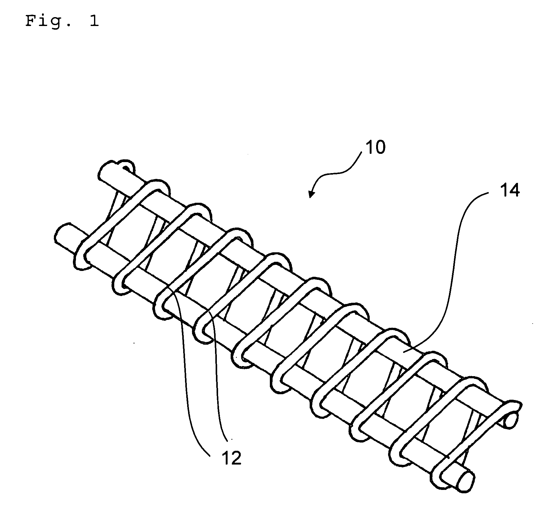
[0035]The schematic illustrations of FIGS. 1 and 5 show a perspective detail-view and top-view of an embodiment of a conveyor belt 10 of an inventive conveying device. The conveyor belt 10 is made of metal wire, for example steel wire, which is covered with PTFE plastic of a defined thickness and processed to form a meshed belt. The illustrations of FIGS. 1 and 5 show an exemplary geometry of the belt 10, which may obviously have a large number of different designs (see for example FIGS. 6 to 9). The supporting structure 22 of the conveyor belt 10 comprises a thinner winding wire 12 which is supported by transverse wires 14. The top level points of the thinner winding wire 12 and transverse wires 14 form the contact areas 18 for the packs being transported.

[0036]The schematic illustrations of FIGS. 6 and 7 show a conveyor chain 10 with a different geometry of the supporting structure 22 compared to FIGS. 1 and 5. The supporting structure 22 of conveyor chain 10 is also of metal. The...


PUM


Abstract

A conveying device and a packaging machine for beverage containers are disclosed. The beverage containers are grouped as packs and wrapped with film, comprising a horizontal conveying device including an endlessly circulating conveyor chain whose movable members and / or meshes each have a supporting structure and contact areas for the packs and / or coatings that include significant portions of PTFE plastic. The contact areas of plastic have a thickness corresponding to at least 10% of the thickness of the supporting structure covered and / or coated therewith

Description

CROSS REFERENCE TO RELATED APPLICATIONS[0001]This claims the benefit of German Patent Application No. 10 2008 023 940.2, filed on May 16, 2008 and hereby incorporated by reference herein.[0002]The present invention relates to packaging machine for packs of beverage containers and a conveying device of such a packaging machine.BACKGROUND[0003]For the packaging of packs of several beverage containers and / or bottles, the beverage containers and / or bottles are grouped on horizontal conveying means and arranged in groups having a defined number of containers. This defined number of grouped containers is usually provided with a film wrapping for more convenient handling so that the packs may be easily transported, stacked and, if necessary, also presented in a sales room in this pack form.[0004]The film wrapping is wrapped around the pack with the help of suitable means and subsequently shrunk by way of heating such that the pack is tightly enclosed by the taut film so that it may be easi...

Claims


Application Information

Patent Timeline
IPC IPC(8): B65B53/02B65G15/54
CPCB65G15/34B65G17/064B65G15/54B65G15/38
Inventor NAPRAVNIK, CHRISTIAN
Owner KRONES AG
Learn More