Magnetostatic levitation and propulsion systems for moving objects

a technology of moving objects and propulsion systems, which is applied in the direction of machines/engines, electric generator control, transportation and packaging, etc., can solve the problems of high cost, high cost, and insufficient magnetic flux to support the weight of the train, so as to eliminate complexity, reduce cost, and reduce the effect of vibration

Inactive Publication Date: 2010-05-27
JI QIGEN
View PDF2 Cites 44 Cited by
  • Summary
  • Abstract
  • Description
  • Claims
  • Application Information

AI Technical Summary

Benefits of technology

[0017]It is also a further object of this invention to provide a novel magnetostatic permanent magnet bearing (MSS PMMB) technology for industrial machines such as compressors, turbines, pumps, motors and generators. A MSS PMMB maglev wind turbine is also a key embodiment under this category. This novel magnetic bearing technology is fully permanent magnet made and features wi

Problems solved by technology

The separation between the vehicle and the guideway must be constantly monitored and corrected by computer systems to avoid collision due to the unstable nature of electromagnetic attraction; due to the system's inherent instability and the required constant corrections by outside systems, vibration issues may occur.
Its propulsion system's functions like a rotating electric motor whose stator is cut open and stretched lengthways along the underside of the full guideway and such infrastructure is quite sophisticated and high expenditure.
At slow speeds, the current induced in these coils and the resultant magnetic flux is not large enough to support the weight of the train.
EDS systems can only levitate the train using the magnets onboard, not propel it forward.
EDS system is unable to levitate vehicles at a standstill, although it can provides levitation down to a much lower speed.
The current Maglev trains are not compatible with conventional track, and therefore require a new infrastructure for their entire route.
This new infrastructure is high expenditure because of the drive or inductive coils must be embedded in the track along its full length.
The weight of the large electromagnets in EMS and EDS is a major design issue.
This MSP LSLM technology provides a low budget long distance and no wheel transportation feasible by eliminating permanent magnets from long stator and possibly expensive position sensor and encoder as well.
With all those merits of the linear motors, but the cost of linear motors are expensive.

Method used


Image

  • Magnetostatic levitation and propulsion systems for moving objects
  • Magnetostatic levitation and propulsion systems for moving objects
  • Magnetostatic levitation and propulsion systems for moving objects

Examples


second embodiment

[0032]FIG. 3 shows schematic description of a MSP long stator linear motor (LSLM) as the present invention. Assembly (a) in FIG. 3 is a schematic cross section and side view of the MSP LSLM that consists of a rotor assembly 48 and a long stator or steel rail assembly 44. The rotor assembly 48 is basically the similar one as illustrated in FIG. 1-2(b) and FIG. 2-2(b) that consists of two pairs of magnets 41 and 42. The magnets are electromagnets or a mixture of permanent magnets and electromagnets. The long stator or steel rail is made of alternating magnetic block 46 and nonmagnetic block 47 on a spacing pattern for the reasons above discussed. The electromagnets can be switched on or off by flowing a current with a waveform like 49 in FIG. 3(b) to match alternative positioning of the magnetic block 46 in between to pick up one direction propulsion force desired. By changing this matching the rotor or vehicle's acceleration or deceleration or applying brake can be functioned. The po...

third embodiment

[0033]FIG. 4 shows a schematic cross-section and side views of a MSS permanent magnet magnetic bearing (PMMB) system as the present invention. The whole structure is round along a shaft axis. The system consists of two sets of the MSS assemblies 61 and 62 with each set located at each end of a nonmagnetic shaft axis 63. The assembly 61 is to provide the shaft assembly 63 a horizontal spring-like balance force and the assembly 62 is to provide the shaft assembly 63 a spring-like vertical suspension. The assemblies are made of a bearing chock 64 or 65 and a steel ring assembly 66 or 67. Inside the bearing chocks there are two pairs of magnet rings aligned as illustrated to produce a spring-like force on the steel rings 66 and 67. The existence of the unstable rightward or leftward forces discussed above makes it a challenging in designing a MSS PMMB product, but a carefully design can still lead to a fully standstill suspension of the shaft assembly 63 and makes it spin around its axi...

fourth embodiment

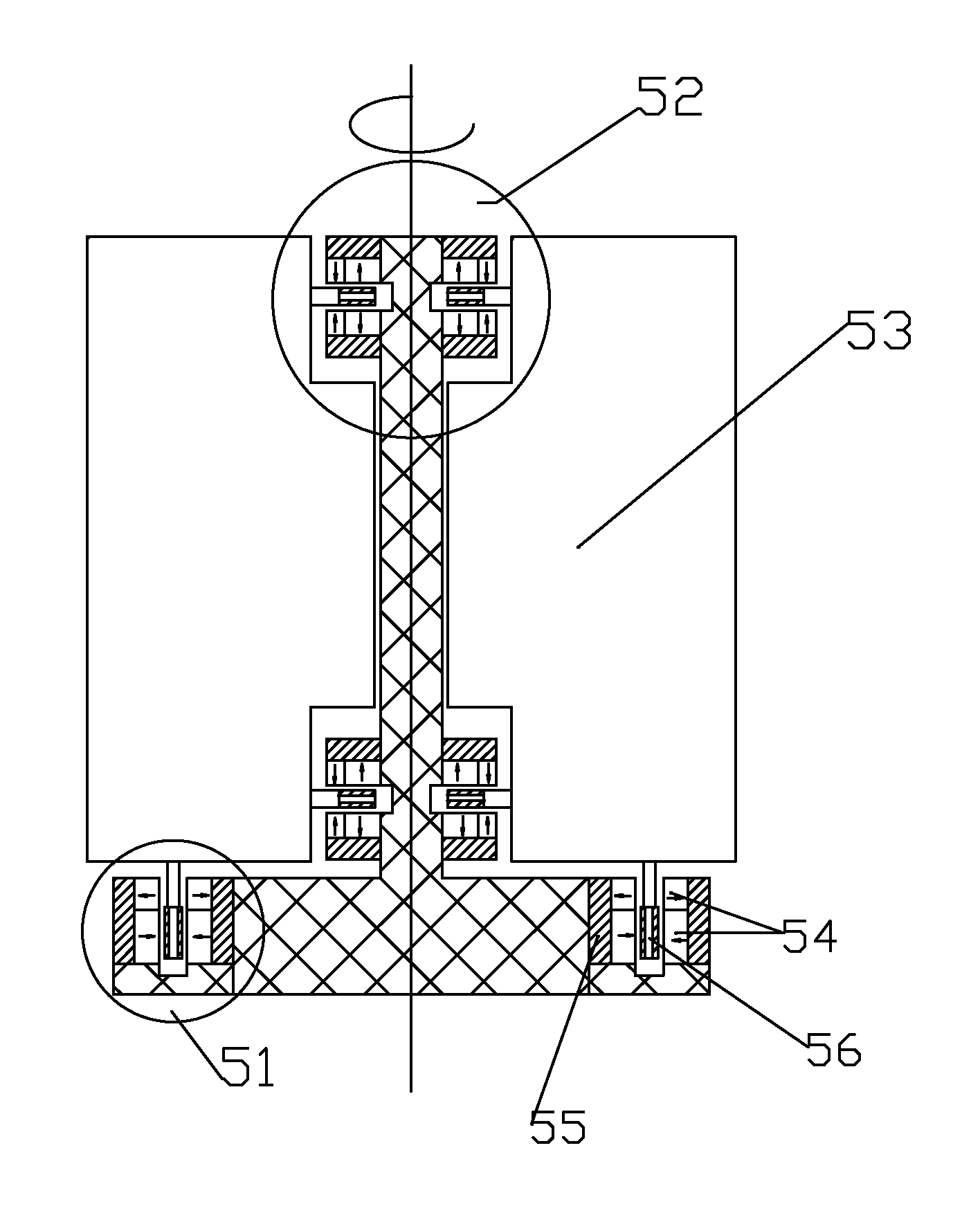
[0034]FIG. 5 shows a schematic cross section of a MSS maglev wind turbine as the present invention. The turbine consists of a MSS assembly 51 and two MSS assembly 52. Weight of the turbine 53 is levitated up through the assembly 51 and its rightward or leftward forces are offset through the assembly 52. The assemblies consist of magnets 54, a flux return steel path 55 and steel ring assembly 56. All magnets are operatively attached to a base or foundation of the wind turbine rather than to the turbine body that has great meaning to lightweight the turbine load or inertia. A number of such assemblies might be used to meet a desired weight lifting power. In this design the turbine body can freely move vertically without a gap limitation that makes big sense in allowing a bigger weight variation or moving vibration during operation or loose manufacturing tolerances.


PUM


Abstract

The present invention relates to a novel magnetic suspension and propulsion technologies, which are named as Magnetostatic Suspension (MSS) and Magnetostatic Propulsion (MSP) respectively because of their magnetostatic nature of forces generated. A spring-like magnetic force is produced through interactions between magnets and ferrous materials such as steel. To apply the technologies, four key embodiments of the invention have been invented and described: a MSS and MSP maglev vehicle system in which a vehicle body is lifted up and stabilized by magnetostatic forces above a steel rail both horizontally and vertically; a MSP long-stator linear motor system in which a rotor can be driven up along a magnet-free steel rail or long steel stator; a MSS Permanent Magnet Magnetic Bearing System (PMMB) system in which a steel shaft is levitated standstill by a fully permanent magnets assembly for frictionless rotating; a MSS maglev wind turbine system in which a magnet-free turbine body can hover standstill over a permanent magnet base assembly spinning frictionlessly with low inertia and low cut-in wind speed threshold.

Description

CROSS-REFERENCE TO RELATED APPLICATIONS[0001]This application is a continuation-in-part of U.S. patent application Ser. No. 12 / 276,406 filed on Nov. 23, 2008 entitled “MAGNETOSTATIC LEVITATION AND PROPULSION SYSTEMS FOR MOVING OBJECTS”.FIELD OF THE INVENTION[0002]The present invention relates to novel magnetostatic suspension and magnetostatic propulsion technologies. A spring-like magnetic force is produced through interactions between magnets and ferrous materials such as steel, which can be used to levitate and / or propel a moving object over a magnet-free steel rail.BACKGROUND OF THE INVENTION[0003]The present invention basically relates to a magnetostatic suspension (MSS) and magnetostatic propulsion (MSP) mechanisms between magnets and ferrous or steel rail tracks or shafts, and more specifically, to a magnetostatic suspension and propulsion mechanisms for moving objects, and further more specifically, to a MSS and MSP maglev vehicle technology, in which a vehicle is suspended ...

Claims


Application Information

Patent Timeline
IPC IPC(8): B60L13/04H02K41/02H02K7/09F03D9/00
CPCB61B13/08B60L2200/26Y02E10/725Y02E10/72
Inventor JI, QIGEN
Owner JI QIGEN
Why Eureka
Try Eureka