
Surface having a nanoporous coating, methods of manufacture thereof and articles comprising the same

a nanoporous coating and surface technology, applied in the direction of semiconductor/solid-state device details, lighting and heating apparatus, transportation and packaging, etc., can solve the problems of localized overheating of the heating surface, low temperature, and reduced heat transfer efficiency, so as to improve the critical heat flux

Inactive Publication Date: 2010-05-27
GENERAL ELECTRIC CO
View PDF1 Cites 14 Cited by
  • Summary
  • Abstract
  • Description
  • Claims
  • Application Information

AI Technical Summary

Benefits of technology

[0007]Disclosed herein is an article comprising a substrate; and a nanoporous coating disposed thereon; the nanoporous coating having a thickness of about 5 nanometers to about 10 micrometers; where an interface between the substrate and the nanoporous coating is disposed at an angle of about 60 degrees to about 120 degrees to a horizontal; the nanoporous coating being in contact with a liquid; the nanoporous coating being operative to improve the critical heat flux by an amount of about 20% to about 100% over a surface that does not have a nanoporous coating.

Problems solved by technology

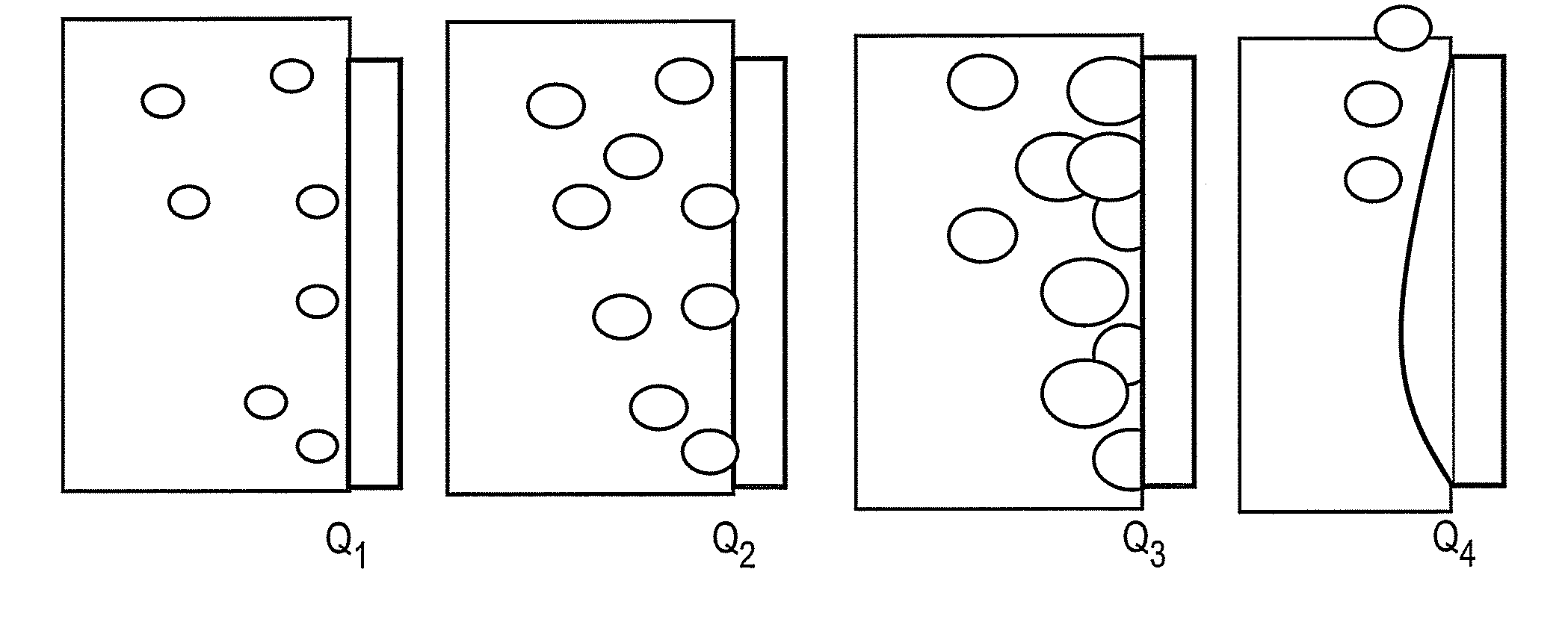
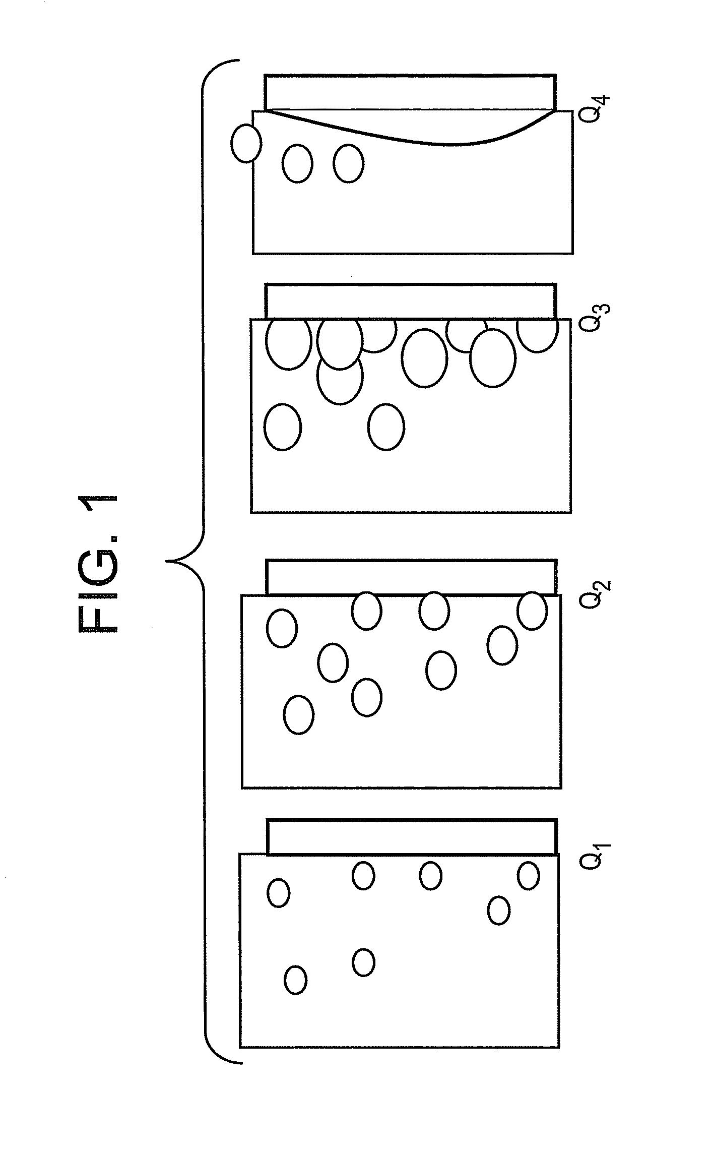
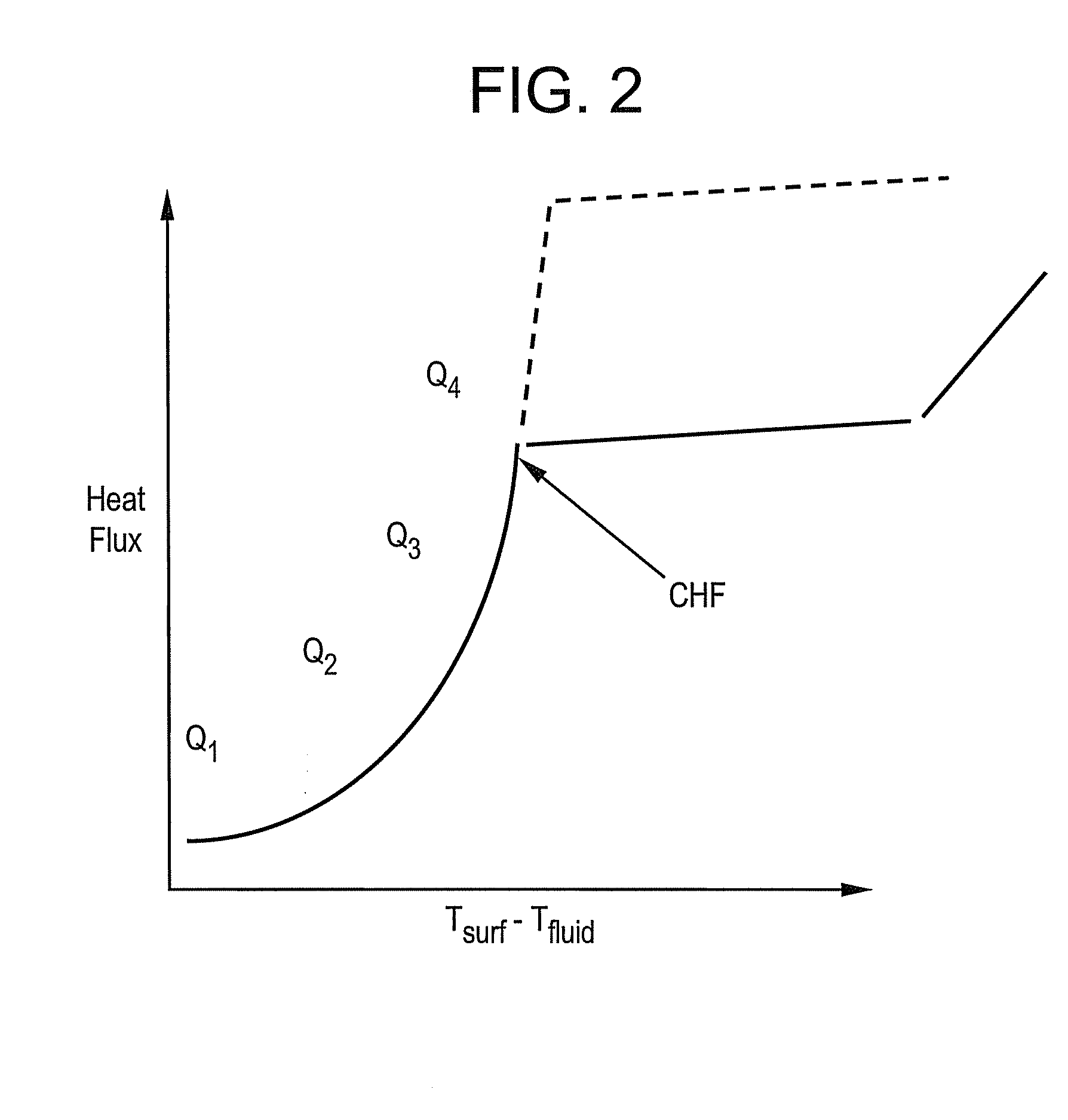
Critical heat flux (CHF) describes the thermal limit of a phenomenon where a phase change occurs during heating (such as bubbles forming on a metal surface used to heat water), which suddenly decreases the efficiency of heat transfer, thus causing localized overheating of the heating surface.
When critical heat flux is achieved, a very small increase in heat flux causes a dry-out, which results in very high temperature rise.
For example, during the transfer a heated fluid in a horizontal direction, gravity causes the fluid to stay in contact with the horizontal surface, which can delay the onset of critical heat flux.
It is more difficult to control critical heat flux on vertical surfaces.
The buoyancy of heated fluids tends to drive the fluid away from a vertical surface thus leading to an early onset of the critical heat flux condition.
In addition, gravity does not facilitate the retention of contact between the fluid and the surface as it does in the case of horizontal surfaces.

Method used


Image

  • Surface having a nanoporous coating, methods of manufacture thereof and articles comprising the same
  • Surface having a nanoporous coating, methods of manufacture thereof and articles comprising the same
  • Surface having a nanoporous coating, methods of manufacture thereof and articles comprising the same

Examples


example 1

[0076]In this example, the same alumina as that used in the Comparative Example 1 was disposed in the form of a porous coating upon the nichrome heater. The thickness of the nanoporous coating was approximately 1 micrometer. This new nanoporous coating surface is then used as the boiling surface (in lieu of the polished surface of the nichrome heater of the Comparative Example 1) so that nothing but surface effects exist.

[0077]The nanoporous coating is formed prior to experiments by injecting droplets of nanofluid solutions onto the surface then letting the water content evaporate causing nanoparticles to be left on the surface forming a nanostructured coating. Surfaces prepared using this method are tested 3 times, each with a clean pool of water in the glass vessel, to evaluate the durability of the coating.

[0078]The results are shown in the FIG. 4(b). The FIG. 4(b) (like the FIG. 4(a)) is a graphical plot of heat flux in watts per square centimeter measured as a function of the d...


PUM

PropertyMeasurementUnit
Lengthaaaaaaaaaa
Fractionaaaaaaaaaa
Fractionaaaaaaaaaa

Abstract

Disclosed herein is an that includes a substrate; and a nanoporous coating disposed thereon; the nanoporous coating having a thickness of about 5 nanometers to about 10 micrometers; where an interface between the substrate and the nanoporous coating is disposed at an angle of about 60 degrees to about 120 degrees to a horizontal; the nanoporous coating being in contact with a liquid; the nanoporous coating being operative to improve the critical heat flux by an amount of about 20% to about 100% over a surface that does not have a nanoporous coating.

Description

BACKGROUND OF THE INVENTION[0001]This disclosure relates to a surface having a nanoporous coating, methods of manufacture thereof and articles comprising the same.[0002]When a fluid contained in a vessel is heated to boiling, bubbles nucleate at the surface and depart from the surface thus removing heat from the source. The bubble size and departure frequency depend on the heat flux and temperature.[0003]With reference to the FIGS. 1 and 2, it can be seen that as heat flux Q increases on the surface from Q1 to Q3, the bubbles get larger and nucleation frequency increases. This continues until a critical heat flux point (hereinafter “critical heat flux condition”) Q4 is achieved. Critical heat flux (CHF) describes the thermal limit of a phenomenon where a phase change occurs during heating (such as bubbles forming on a metal surface used to heat water), which suddenly decreases the efficiency of heat transfer, thus causing localized overheating of the heating surface. This decrease i...

Claims


Application Information

Patent Timeline
IPC IPC(8): B32B5/16B32B5/18B05D5/00B05D1/00B05D1/06B05D1/18
CPCB01B1/06B01D1/30C23C24/00F28F13/185H01L2924/0002H01L23/44H01L2924/00Y10T428/249986Y10T428/249953
Inventor ICOZ, TUNCKU, ANTHONY YU-CHUNGRUUD, JAMES ANTHONY
Owner GENERAL ELECTRIC CO
Learn More