A kind of ultra-thin flat heat pipe and its manufacturing method

A technology of flat heat pipes and manufacturing methods, applied in the field of heat pipes, can solve problems such as high channel depth and width requirements, poor anti-gravity operation effect, and easy heat transfer limit, so as to speed up condensation speed, improve efficiency, and improve heat transfer. The effect of thermal extremes

Active Publication Date: 2019-05-31
NORTH CHINA ELECTRIC POWER UNIV (BAODING)
View PDF4 Cites 1 Cited by
  • Summary
  • Abstract
  • Description
  • Claims
  • Application Information

AI Technical Summary

Problems solved by technology

The channel of the grooved liquid-absorbing core provides a channel for liquid return, but the capillary driving force is small, and the requirements for the depth and width of the channel are relatively high; the wire-mesh liquid-absorbing core has good heat transfer performance, but the manufacturing The process is complex; the porous media type liquid-absorbing core can provide greater capillary force and greater heat transfer, but the liquid return resistance is also greater
In the traditional heat pipe with copper wire as the liquid-absorbing core, the sharp-angled area formed between the copper wire and the shell is used as a channel for the liquid to flow back. The processing is relatively simple, but the capillary force provided by the sharp-angled area is limited.
When the thickness of the heat pipe is thin, the traditional heat pipe is easy to reach the heat transfer limit, resulting in deterioration of heat transfer, low critical heat flux, poor anti-gravity operation effect, and poor heat transfer performance

Method used


Image

  • A kind of ultra-thin flat heat pipe and its manufacturing method
  • A kind of ultra-thin flat heat pipe and its manufacturing method
  • A kind of ultra-thin flat heat pipe and its manufacturing method

Examples


Embodiment 1

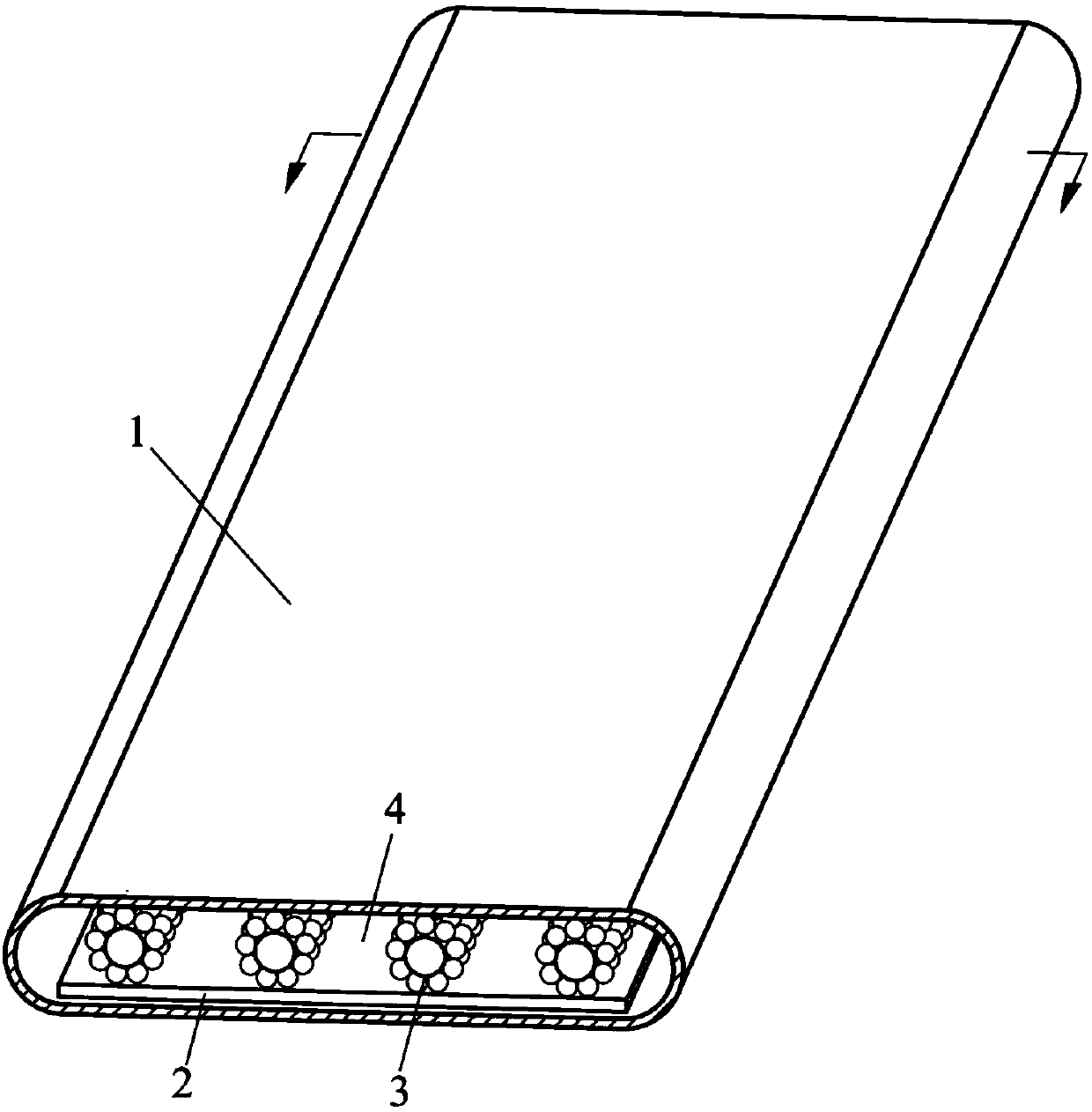
[0071] An ultra-thin flat heat pipe, the manufacturing method is as follows:

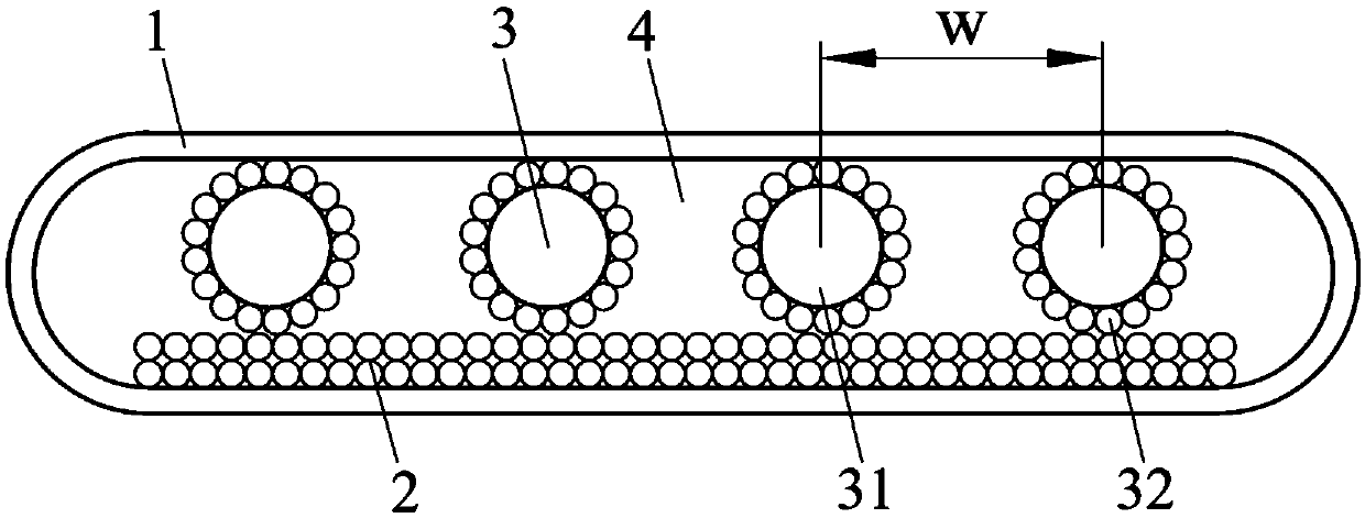
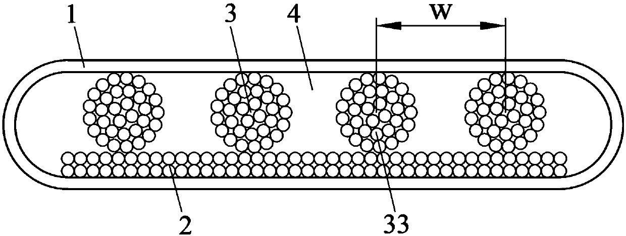
[0072] Step 1, material preparation: cutting the metal sheet 11 and the metal wire 31 of predetermined size, both of which are made of T2 copper. Metal sheet 11 looks like Figure 5 As shown, the length is 200.0mm, the width is 63.0mm, and the thickness is 0.20mm, and it is treated with degreasing and deoxidizing film. The outer diameter of the wire 31 is 0.50 mm.

[0073] Step 2, sintering the bottom layer of the porous medium 2: as Figure 6 As shown, a layer of porous medium bottom layer 2 with a thickness of 0.20 mm is sintered on the left half surface of the metal sheet 11. The specific operation is to fill spherical copper powder with an average particle size of 82.8 μm into the rectangular groove in the graphite mold , control the thickness of the copper powder, press the graphite mold containing the copper powder on the specified position of the metal sheet 11, so that the four side edges...

Embodiment 2

[0079] An ultra-thin flat heat pipe, the manufacturing method is as follows:

[0080] Step one to step four are the same as embodiment 1.

[0081] Step 5: performing superhydrophilic modification treatment on the porous medium bottom layer 2 and porous medium filament 3, and superhydrophobic modification treatment on the condensation surface of the condensation section. The specific modification method is as follows: using the method of chemical oxidation, the porous medium bottom layer 2 and the porous medium filament 3 are subjected to super-hydrophilic treatment, that is, the heat pipe semi-finished product obtained in step 4, only the half side containing the liquid-absorbing core is heated at a temperature of 70 ° C. , immersed in 2.5mol / L KOH and 0.065mol / L K 2 S 2 o 8 reacted in the mixed solution of 30min, so that the contact angle of the metal surface of the liquid-absorbent core is close to 0°. Using the self-assembly method, the condensing surface of the condens...


PUM

PropertyMeasurementUnit
thicknessaaaaaaaaaa
thicknessaaaaaaaaaa
thicknessaaaaaaaaaa

Abstract

The invention relates to an ultra-thin flat heat pipe and a manufacturing method thereof. A wick comprises a porous medium bottom layer and a plurality of porous medium filaments arranged side by side; the porous medium filaments make contact with the top of a tube shell; the wick inside the heat pipe, a sharp angled area between the porous medium filaments and the upper surface of the tube shell, and a sharp angled area between the porous medium filaments and the porous medium bottom layer provide liquid return capillary driving force which is large enough in a limited space; spaces formed between the porous medium filaments provide steam flow channels, and the steam flow channels communicate with one another; and reasonable matching of vapor-liquid phase distribution is achieved, and steam and condensed liquid can flow easily. According to the ultra-thin flat heat pipe, efficient operation can be maintained at various angles, the performance of anti-gravity operation is excellent, the heat flux which can be borne by the heat pipe is high, and the heat transfer performance of the heat pipe is remarkably improved after further modification treatment.

Description

technical field [0001] The invention belongs to the technical field of heat pipes, in particular to an ultra-thin flat heat pipe and a manufacturing method thereof. Background technique [0002] Electronic components are developing towards miniaturization, integration, and high computing speed. For example, the heat flux density of micro electronic components such as mobile phones, notebook computers, and high heat flux chips is getting higher and higher, and their performance will be restricted by heat dissipation. As a phase-change heat transfer device, heat pipes can be self-driven without external energy. They have the advantages of small size, light weight, and high heat transfer performance. They are widely used in the cooling of electronic devices. [0003] The liquid-absorbing core inside the heat pipe mainly includes grooves, wire mesh, porous media, and composite structures. The channel of the grooved liquid-absorbing core provides a channel for liquid return, but...

Claims


Application Information

Patent Timeline
Patent Type & Authority Patents(China)
IPC IPC(8): F28D15/02
CPCF28D15/025F28D15/0283
Inventor 徐进良刘昌泉赵举贵
Owner NORTH CHINA ELECTRIC POWER UNIV (BAODING)
Why Eureka
Try Eureka