
Combined gravity separation-filtration for conducting treatment processes in solid-liquid systems

Inactive Publication Date: 2010-06-03
KHUDENKO BORIS MIKHAIL
View PDF2 Cites 56 Cited by
  • Summary
  • Abstract
  • Description
  • Claims
  • Application Information

AI Technical Summary

Benefits of technology

[0006]This is a method of combined sequential gravity separation-filtration treatment of a solids-liquid mixture for producing treated liquid, wherein gravity separation and filtration steps are conducted in a single volume, the mixture is fed in this volume as a single influent flow and undergoes at least partial clarification in the gravity separation step to produce clarified flow and separated solids. This clarified flow carries the balance of the solids and it is continuously becoming the filtration influent in the sequential step of filtration. The step of filtration is intercepting at least a portion of the balance of solids and is producing a filtration effluent that is evacuated from the combined sequential gravity separation-filtration as a single effluent flow. The transfer of the clarified flow from the gravity separation step to the filtration step is provided without separate collection and transfer of the clarified flow and without distribution of the transferred flow in the filtration step. This method has significant advantages over conventional separate clarifiers with collection of the clarified effluent flow, transfer by pipes and / or flumes of this flow into separate filters, distributing the incoming flow in the filter filled with an attachment medium, with the use of a system of perforated pipes, or more complex and expensive means, filtering and producing the final effluent. As follows from the description at the beginning of this paragraph, the new system can be accommodated in a single combined unit; accordingly, the capital costs will be reduced. The system can be used for upgrading existing clarifiers. The hydraulic loading rate per unit surface of clarifiers is several-fold less than that for filters. Accordingly, filtration sections, or units, or modules can be installed within existing clarifiers. This method can also be easily accommodated in new designs. Considering that the operation of such systems is simpler than conventional systems, there will also be operational savings.

Problems solved by technology

The systems with separate units are expensive because they require larger territories, larger buildings, complex flow distribution piping and flumes, many fittings, valves and gates, and special equipment.
Cloth and membrane filters do not provide large volume and surface area for conducting many chemical, physical-chemical and biological reactions needed for controlling a broad range of constituents in the final treatment steps of the effluent.

Method used


Image

  • Combined gravity separation-filtration for conducting treatment processes in solid-liquid systems
  • Combined gravity separation-filtration for conducting treatment processes in solid-liquid systems
  • Combined gravity separation-filtration for conducting treatment processes in solid-liquid systems

Examples


Embodiment Construction

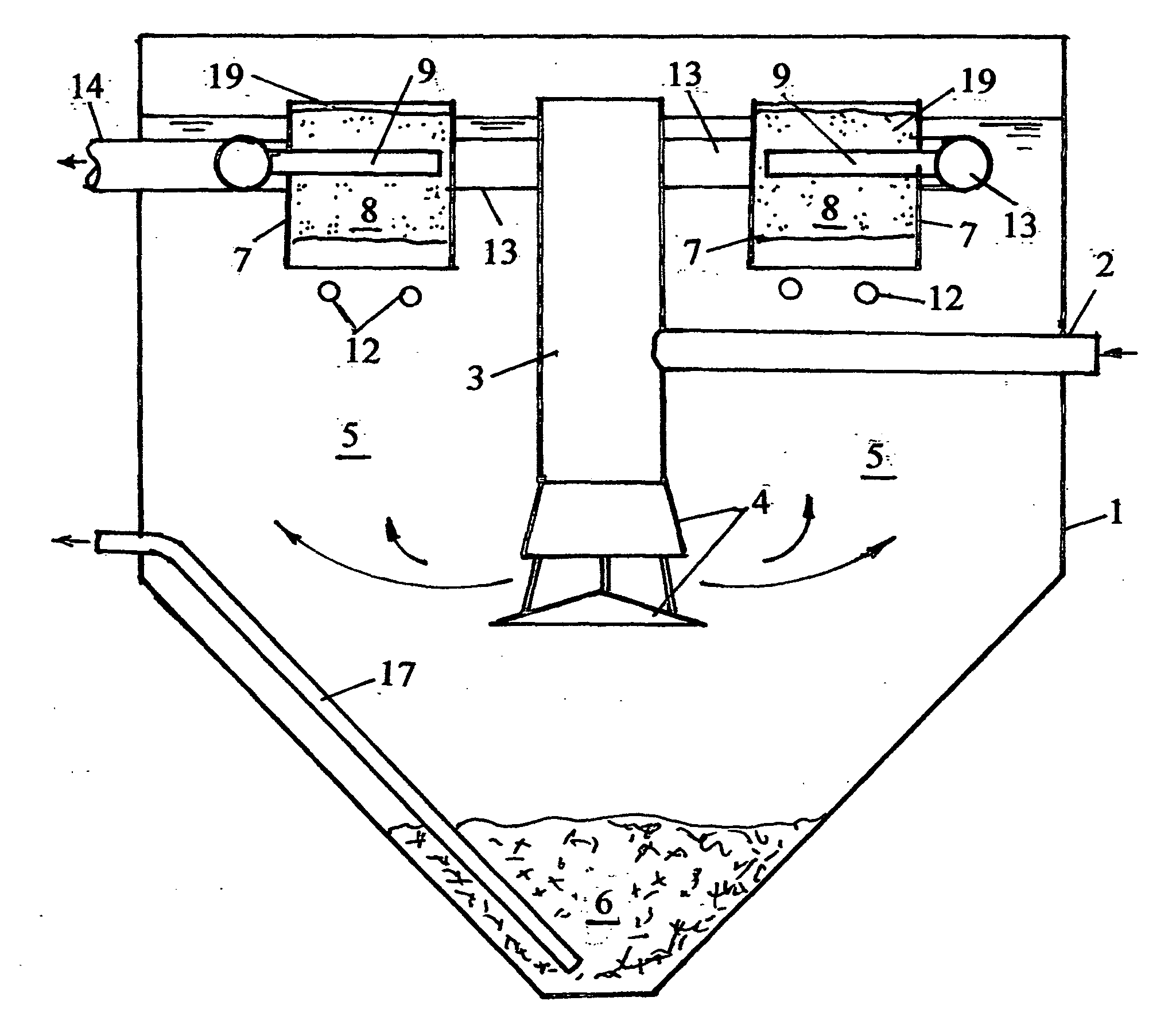
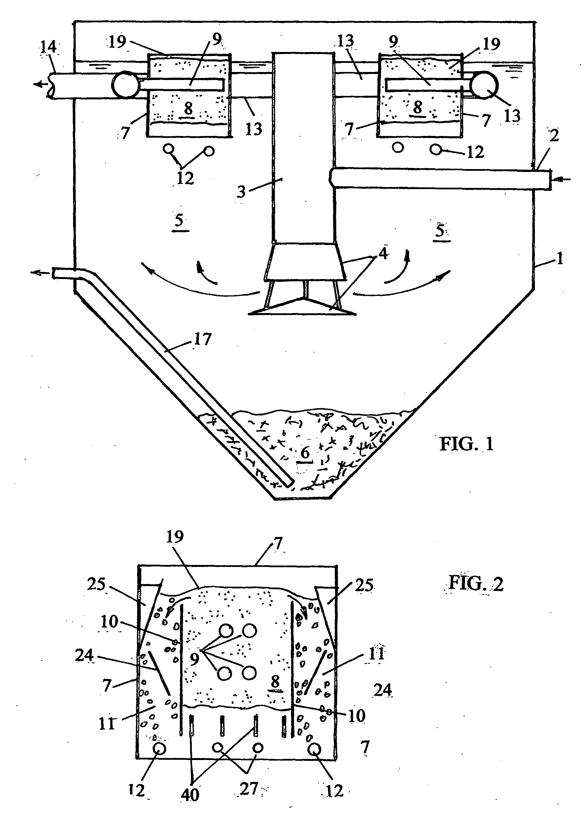
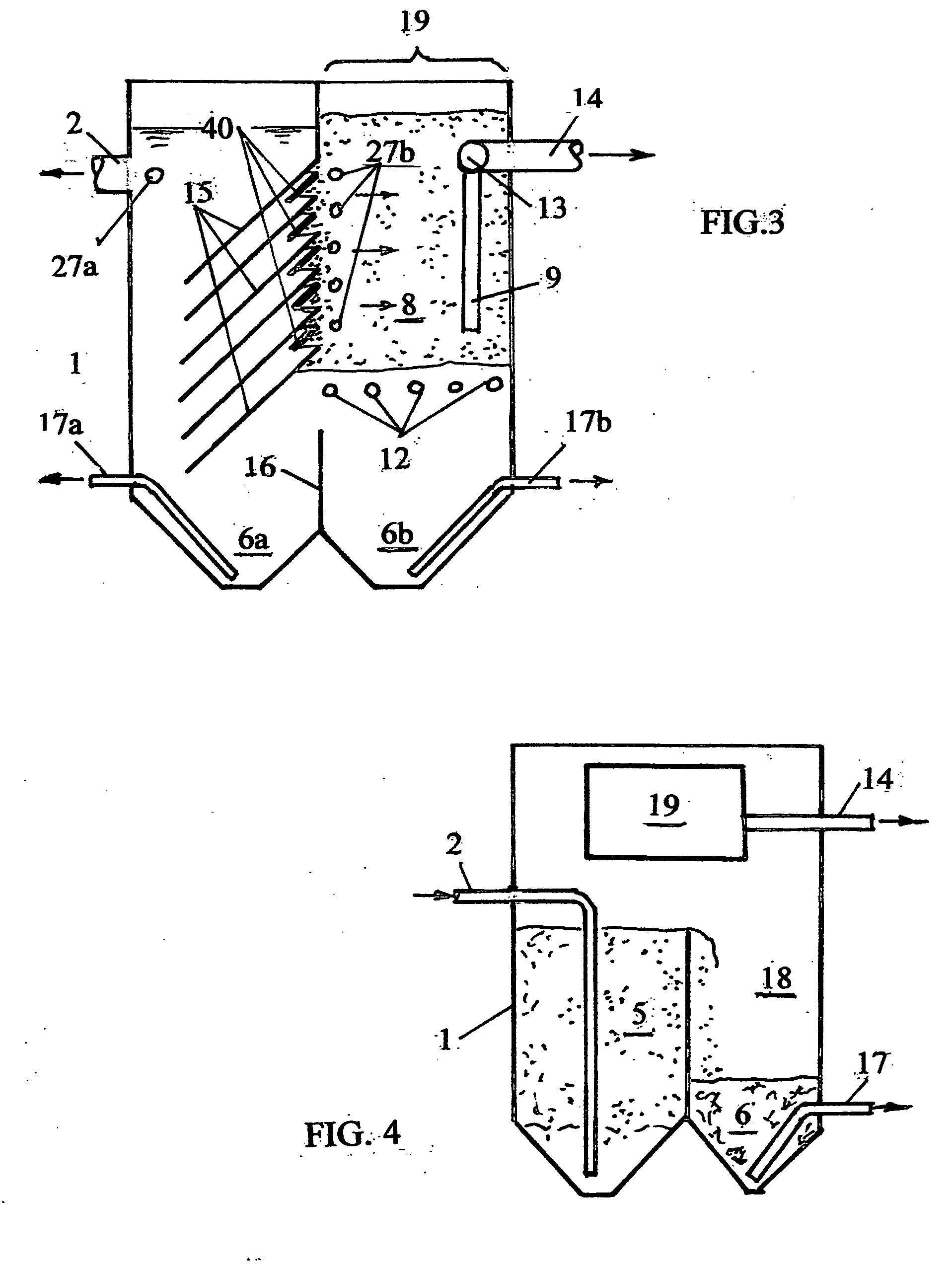
[0039]FIG. 1 is a vertical section of a combination of a clarifier 1 with vertical flow of solid-liquid mixture and a single-section filtration modules 19 built-in the clarifier above the clarification zone 5. One or several filtration modules 19 can be installed in the upper section of the clarification zone 5. Each filtration module 19 is enclosed by side walls 7 and has open top and bottom, therefore, the clarification zone 5 is in direct communication with the filtration zone 8. A feed pipe 2 for the influent solid liquid mixture is connected to a feed well 3 with a flow distributor 4 submerged at the lower level of the clarification zone 5. After the flow distributor 4, the influent flow rises through the clarification zone 5, the suspended solids heavier than water are settling down across zone 5 and become collected in sludge zone 6, from where the sludge is evacuated by a line 17. At least partially clarified solid-liquid mixture enters the filtration modules 19 from the ope...


PUM

PropertyMeasurementUnit
Fractionaaaaaaaaaa
Volumeaaaaaaaaaa
Mechanical propertiesaaaaaaaaaa

Abstract

This is a method and apparatus for combined gravity separation-filtration for conducting physical, physical-chemical, chemical, and biological processes in solid-liquid systems; including but not limited to separation of dispersed solids from liquids, separation of alkalinity from the liquid stream, chemical acid-base interactions, chemical oxidation-reduction, chemical dissolution-precipitation, physical chemical adsorption, ion exchange, mass transfer in any combinations of multiple liquid-solid-gas phases, biological oxidation-reductions, biological growth, and combinations of these processes; gravity separation steps can be conducted in rectangular horizontal unidirectional flow clarifiers, rectangular or circular radial flow clarifiers, rectangular or circular vertical flow clarifiers, lamella clarifiers, suspended sludge blanket clarifiers, fluidized bed separators, and combinations thereof, wherein the filtration step is disposed in the upper portion of the combined process or side-by-side with clarification step; filtration steps are conducted in single or multiple attachment media filters, including particulate filter media either heavier than liquid or floating; liquid filtered through the attachment media is collected by holed pipes, screens, or membranes. Reagents can be introduced before the gravity separation and / or before filtration steps. This method and apparatus can be used for municipal and industrial water purification and wastewater treatment for removal of a broad range of admixtures including BOD / COD, suspended solids, nitrogen and phosphorus, organics imparting color, salts of hardness, heavy metals, and other constituents of admixture.

Description

RELATED APPLICATIONS[0001]This is a Continuation in Part (CIP) of now allowed U.S. application Ser. No. 11 / 893,872.FIELD OF INVENTION[0002]This is a method and apparatus for treatment of municipal and industrial water and wastewater in combined gravity separation-filtration process steps for conducting physical, physical-chemical, chemical and biological treatment processes.PRIOR ART[0003]Water and wastewater treatment systems often include steps of gravity separation of suspended solids from water as a crude clarification step, followed by filtration for a thorough removal of the residual solids.[0004]In typical water purification plants, the initial treatment is conducted by coagulating and flocculating the suspended particles in the influent followed by the crude gravity separation of the formed flocks in gravity separators or clarifiers of one or another kind. These flocks also adsorb at least a portion of he dissolved solids, for example humic and fulvic acids. In the subsequen...

Claims


Application Information

Patent Timeline
IPC IPC(8): C02F9/08C02F101/10C02F101/30C02F103/02C02F103/06C02F103/20C02F103/26
CPCB01D24/06B01D2311/04B01D2315/06C02F1/004C02F1/444B01D2311/2649
Inventor KHUDENKO, BORIS MIKHAIL
Owner KHUDENKO BORIS MIKHAIL
Learn More