

Semiconductor Chip Laminate and Adhesive Composition for Semiconductor Chip Lamination
- Summary
- Abstract
- Description
- Claims
- Application Information
AI Technical Summary
Benefits of technology
Problems solved by technology
Method used
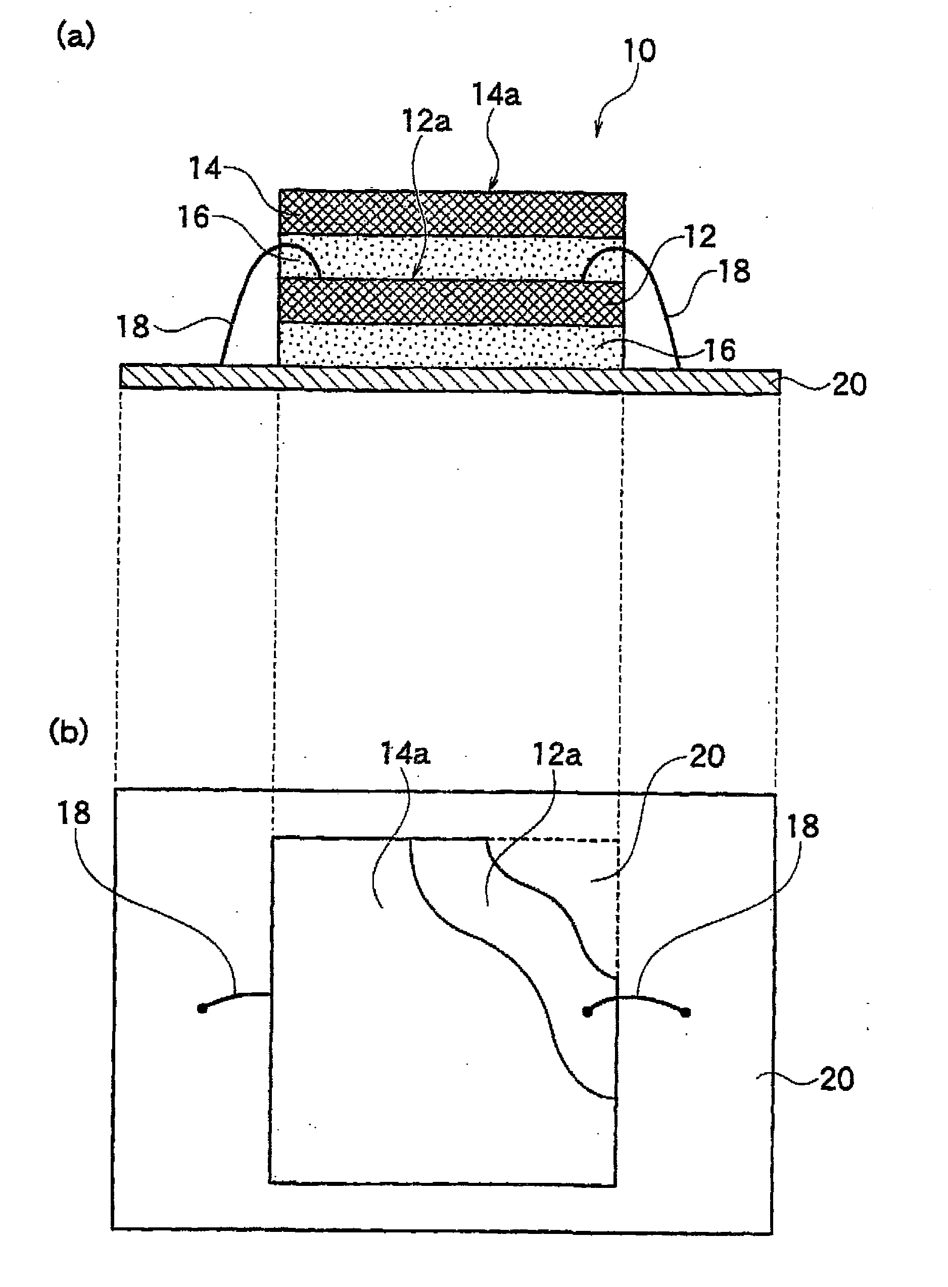
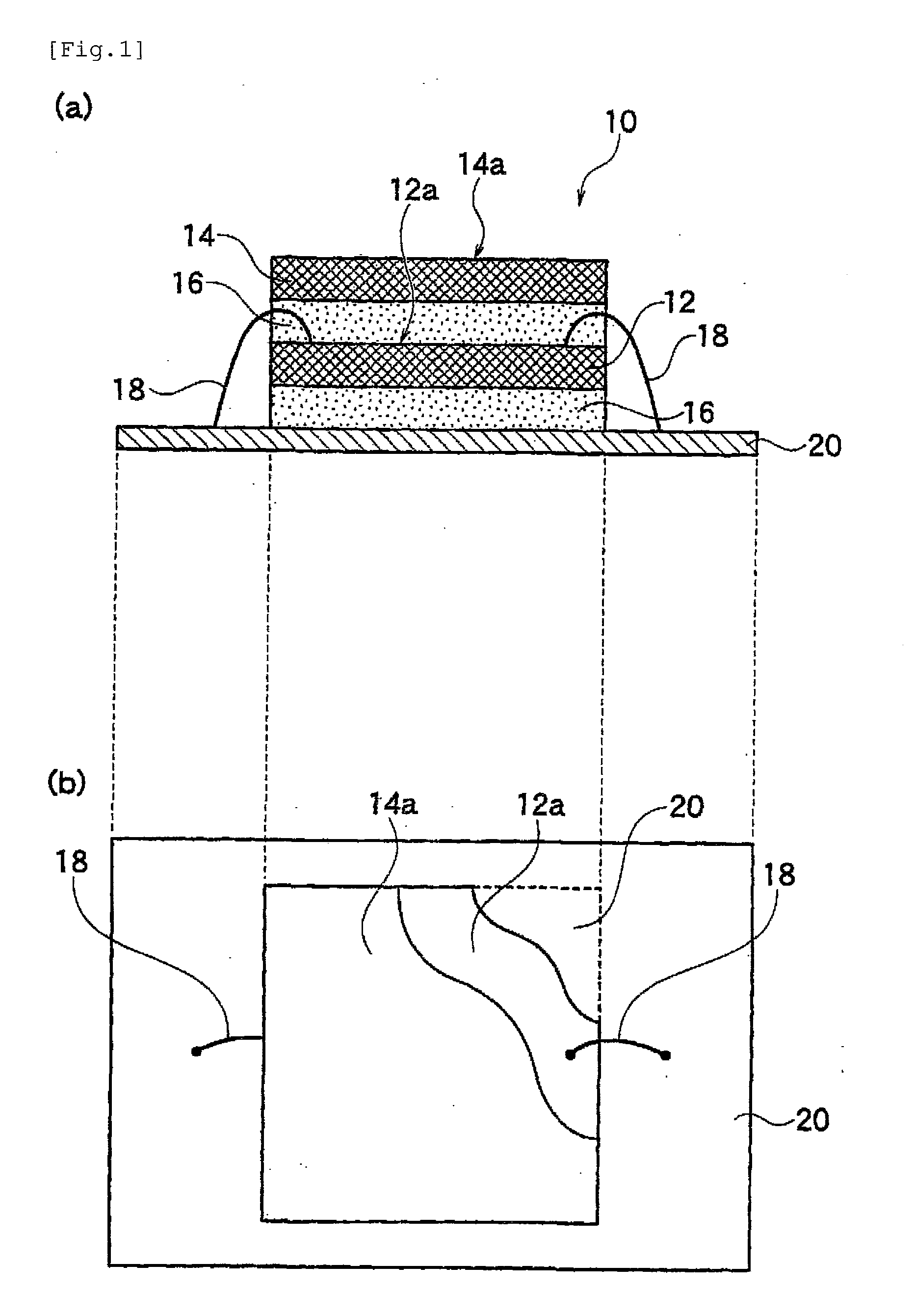
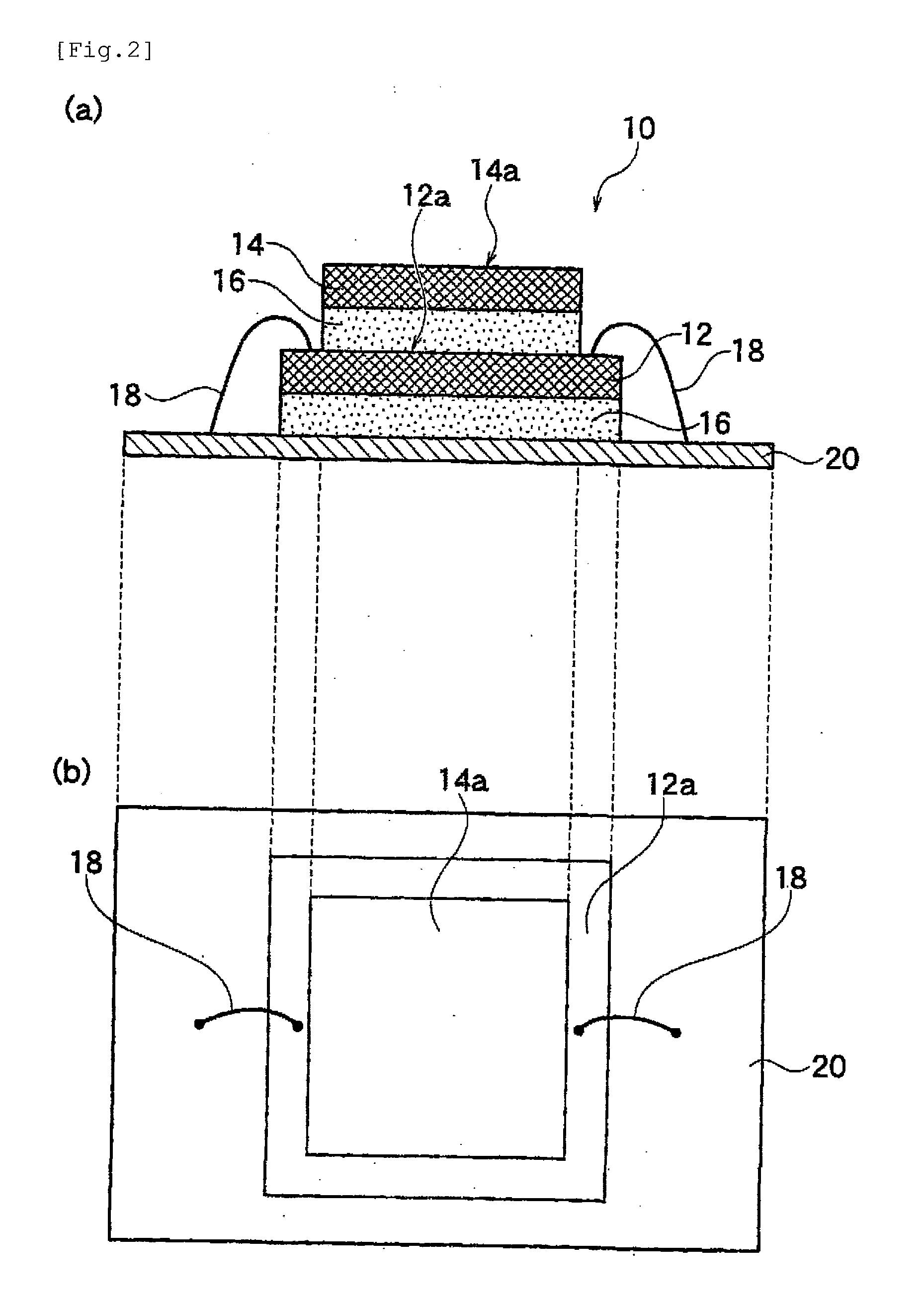
Image

Examples
examples
[0114]The present invention will now be described with Examples, but is not limited to Examples.
(1) Manufacturing of Adhesive Sheet for Semiconductor Chip Lamination
[0115]Each of adhesive compositions used for adhesive sheets for semiconductor chip lamination of Examples and Comparative Examples includes the following components. Table 1 shows the component ratio. In the table, numerical values are expressed as parts by weight in terms of a solid content (non-volatile component).
(A) acrylic polymer: COPONYL N-2359-6 available from The Nippon Synthetic Chemical Industry Co., Ltd. (Mw: about 300,000)
(B-1) liquid epoxy resin: bisphenol A epoxy resin (Eposet BPA328 available from NIPPON SHOKUBAI CO., LTD., epoxy equivalent 235 g / eq)
(B-2) solid epoxy resin: phenol novolac epoxy resin (EPPN502H available from Nippon Kayaku Co., Ltd., epoxy equivalent 167 g / eq)
(C) thermal curing agent: novolac phenolic resin (Shonol BRG-556 available from SHOWA HIGHPOLYMER CO., LTD., phenolic hydroxyl grou...
PUM
| Property | Measurement | Unit |
|---|---|---|
| Percent by mass | aaaaa | aaaaa |
| Percent by mass | aaaaa | aaaaa |
| Shape | aaaaa | aaaaa |
Abstract
Description
Claims
Application Information