Hole jet reactor and a process for the preparation of an isocyanate using the reactor

a technology of isocyanate and reactor, which is applied in the preparation of isocyanic acid derivatives, gas-gas reaction processes, separation processes, etc., can solve the problems of obstructing gas flow, obstructing channel, and requiring considerable safety precautions in the reactor, so as to improve the mixing effect, reduce the kinetic energy of the reaction materials, and accelerate the reaction rate

Active Publication Date: 2010-06-03
WANHUA CHEMICAL (NINGBO) CO LTD
View PDF8 Cites 10 Cited by
  • Summary
  • Abstract
  • Description
  • Claims
  • Application Information

AI Technical Summary

Benefits of technology

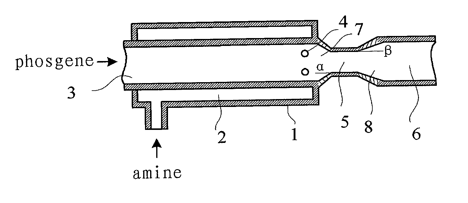
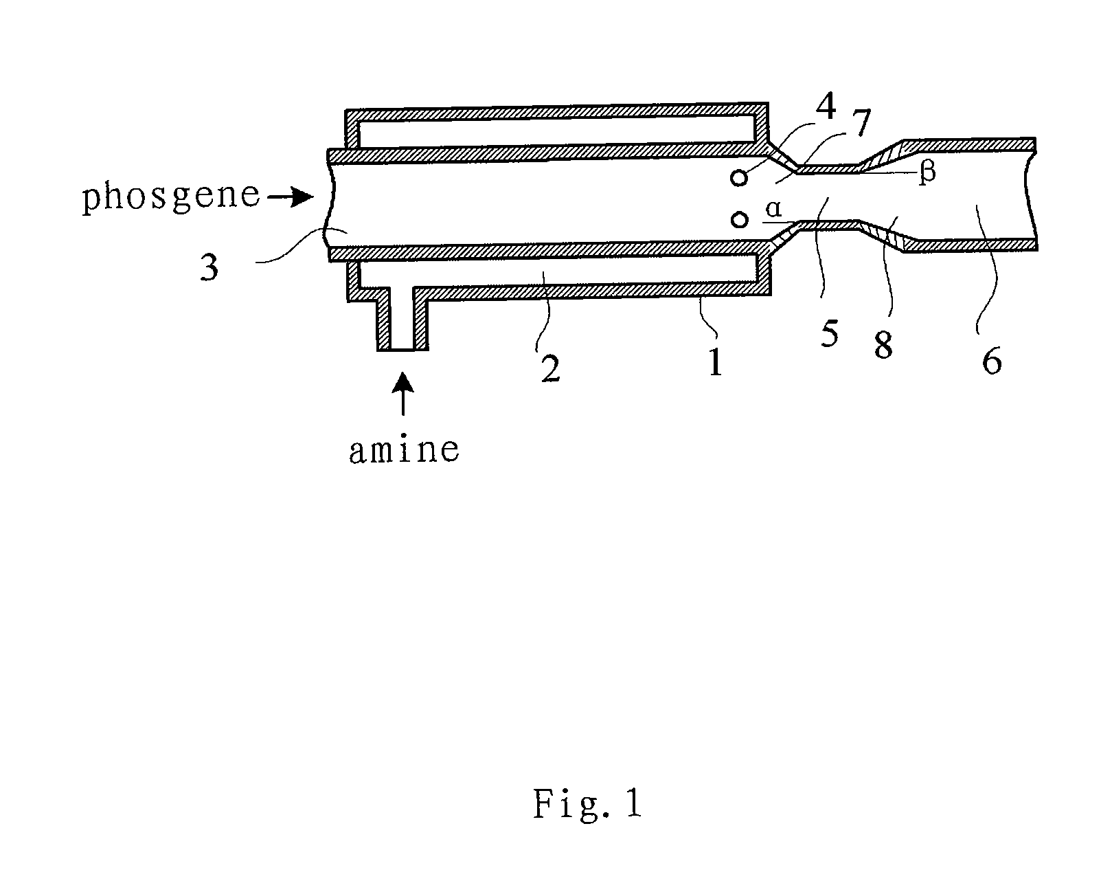
[0029]As for the gas-phase phosgenation reaction at a high temperature, solid particles once formed in the reactor will be carbonized and coked, and it is difficult to remove the coked substance simply by flushing with the reaction materials, because of the faster reaction rate than that of a liquid-phase reaction and the low kinetic energy of the reaction materials in the mixing reaction area of the reactor. Thus, it is desired to enhance the mixing effect and prevent solid particles formed due to back-mixing from blocking the reactor as well. The reactor of the present invention is provided with a mixing area with a convergent channel, a necking tube, and a divergent channel. This mixing area is similar to a venturi tube in shape. This structure can increase the gas velocity and avoid back-mixing or whirling of the reactants, thus avoiding buildup and deposition of solid particles. Particularly, the reactor of the present invention is provided with the convergent channel between the internal feed tube and the necking tube; and the holes are arranged at the downstream part of the internal feed tube and close to the beginning of the convergent channel as far as possible, or in the wall of the convergent channel. When amine stream is jetted into phosgene stream through the holes, such a structure can reduce the possibilities of forming swirls and eliminate negative pressure produced at local jet areas. As such, a good mixing and reacting result can be obtained in the gas-phase phosgenation reaction of the present invention by reducing back-mixing and avoiding the forming of solid by-products.

Problems solved by technology

However, the reactor requires considerable safety precaution.
However, due to back-mixing of the reactants, isocyanates may react with amines to form solid deposit in the reactor, which may obstruct the gas flow.
However, due to the small size of the channel, there is a risk that a polymer produced at a high temperature may block the channel.
Polymer by-products may be produced if the mixing of the gaseous reactants is not efficient enough.

Method used


Image

  • Hole jet reactor and a process for the preparation of an isocyanate using the reactor
  • Hole jet reactor and a process for the preparation of an isocyanate using the reactor

Examples


example 1

[0042]Phosgene, heated to 360° C., flowed continuously into the reaction tube at a rate of 12 m / s through the internal feed tube. At the same time, a mixture, heated to 360° C., of 4,4′-diaminodicyclohexylmethane (H12MDA) and nitrogen was jetted at the rate of about 42 m / s into the phosgene stream through 6 holes made in the wall of the internal feed tube. The mole ratio of H12MDA:phosgene:nitrogen was 1:6:1. The jetting directions of the holes were all perpendicularly aimed at the axis of the internal feed tube, i.e. the center of the phosgene stream flow. The diameter of each of the holes was 1 mm; the internal feed tube was measured 8 mm in inner diameter and 2 mm in wall thickness; the inner diameter of the external feed tube was 16 mm (the thickness of the annular space was 2 mm); the necking tube was measured 5 mm in inner diameter and 20 mm in length; and the pressure inside the reaction tube was 400 mbar. The reactor was connected at the downstream part thereof with an isocy...

example 2

[0043]Phosgene, heated to 360° C., flowed continuously into the reaction tube at the rate of 8 m / s through the internal feed tube. At the same time, a mixture, heated to 360° C., of H12MDA and nitrogen was jetted at the rate of about 25 m / s into the phosgene stream through 4 holes made in the wall of the internal feed tube. The mole ratio of H12MDA:phosgene:nitrogen was 1:6:1. The diameter of each of the holes was 2 mm; the internal feed tube was measured 12 mm in inner diameter and 2 mm in wall thickness; the inner diameter of the external feed tube was 18 mm; the necking tube was measured 5 mm in inner diameter and 20 mm in length; and the pressure inside the reaction tube was 400 mbar. The vapors emerging from the reaction tube of the reactor were condensed and separated under the process conditions of Example 1. The yield of H12MDI was 97.6% of the theory.

example 3

[0045]Isophoronediamine (IPDA) was reacted with phosgene under the same process conditions of Example 1. The mole ratio of IPDA:phosgene:nitrogen was 1:6:1. The reactor was the same as that in Example 1. Before entering the reactor, phosgene and a mixture of IPDA and nitrogen were separately preheated to 310° C. The yield of IPDI was 98.6% of the theory.


PUM

PropertyMeasurementUnit
distanceaaaaaaaaaa
angleaaaaaaaaaa
velocityaaaaaaaaaa

Abstract

The present invention relates to a hole-jetting type reactor and its applications, in particular to a process for the production of isocyanates by the phosgenation of aliphatic or aromatic diamines or triamines in the gas phase using this reactor. The present invention achieves a good mixing and reacting result of the gas-phase phosgenation reaction at a high temperature by improving the mixing of reactants in the reactor to reduce the possibility of forming swirls and eliminate negative pressure produced at a local jet area, which can finally reduce back-mixing and formation of solid by-products.

Description

FIELD OF THE INVENTION[0001]This invention relates to a hole-jetting type reactor and its applications, in particular, to a process for the production of isocyanates by the phosgenation of aliphatic or aromatic diamines or triamines in the gas phase using this reactor.BACKGROUND OF THE INVENTION[0002]The preparation of isocyanates by the reaction of amines with phosgene in the gas phase has been reported as early as in the 1940's (see Siefken, Annalen 562, 108, 1949). The phosgenation reaction is a fast reaction process and usually carried out in a tube reactor. The gas-phase phosgenation requires a fast mixing rate and simultaneously avoid blockage of the reactor under high temperature as far as possible.[0003]GB 1,165,831 describes a process for the gas-phase phosgenation of amines in vapor form with phosgene is carried out at a temperature of 300° C. in a tube reactor equipped with mechanical stirrer, which can prevent a build-up of polymer by-products on the wall of the tube. Ho...

Claims


Application Information

Patent Timeline
Patent Type & Authority Applications(United States)
IPC IPC(8): C07C263/10B01J19/26
CPCB01F5/0473B01F5/048B01F5/0646B01F5/0652B01J4/002B01J19/26B01J2219/00119C07C2101/14B01J2219/00247B01J2219/00252B01J2219/00254C07C263/10C07C265/14C07C2601/14B01F25/3141B01F25/31423B01F25/433B01F25/4335
Inventor DING, JIANSHENGSHANG, YONG HUAMA, DEQIANGHAO, JINGQUANLUO, PEICHENGHU, SHUANG
Owner WANHUA CHEMICAL (NINGBO) CO LTD
Why Eureka
Try Eureka