[0035]In the refrigeration apparatus of the present invention capable of operating, without the use of the heat source-side
heat exchanger (15), in a 100% heat
recovery operation mode in which the second utilization-side heat exchanger (21) and the first utilization-side heat exchanger (31, 41) function respectively as a condenser and as an
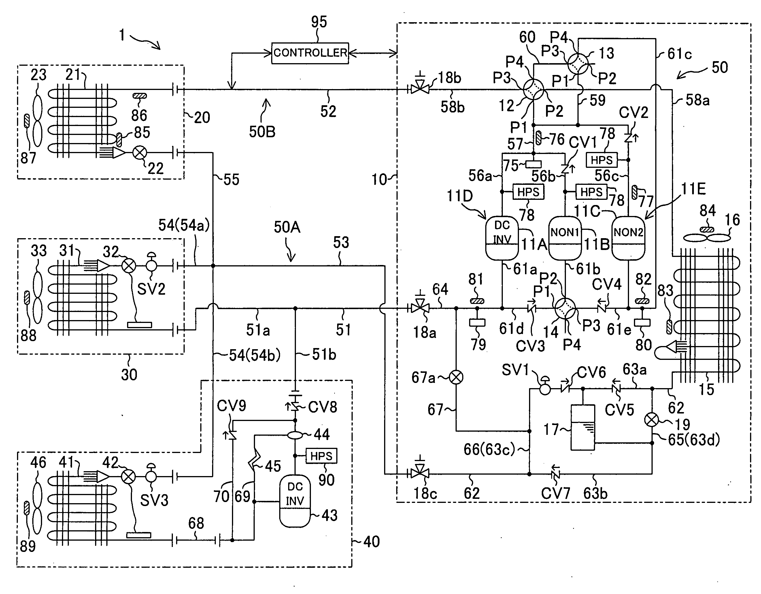
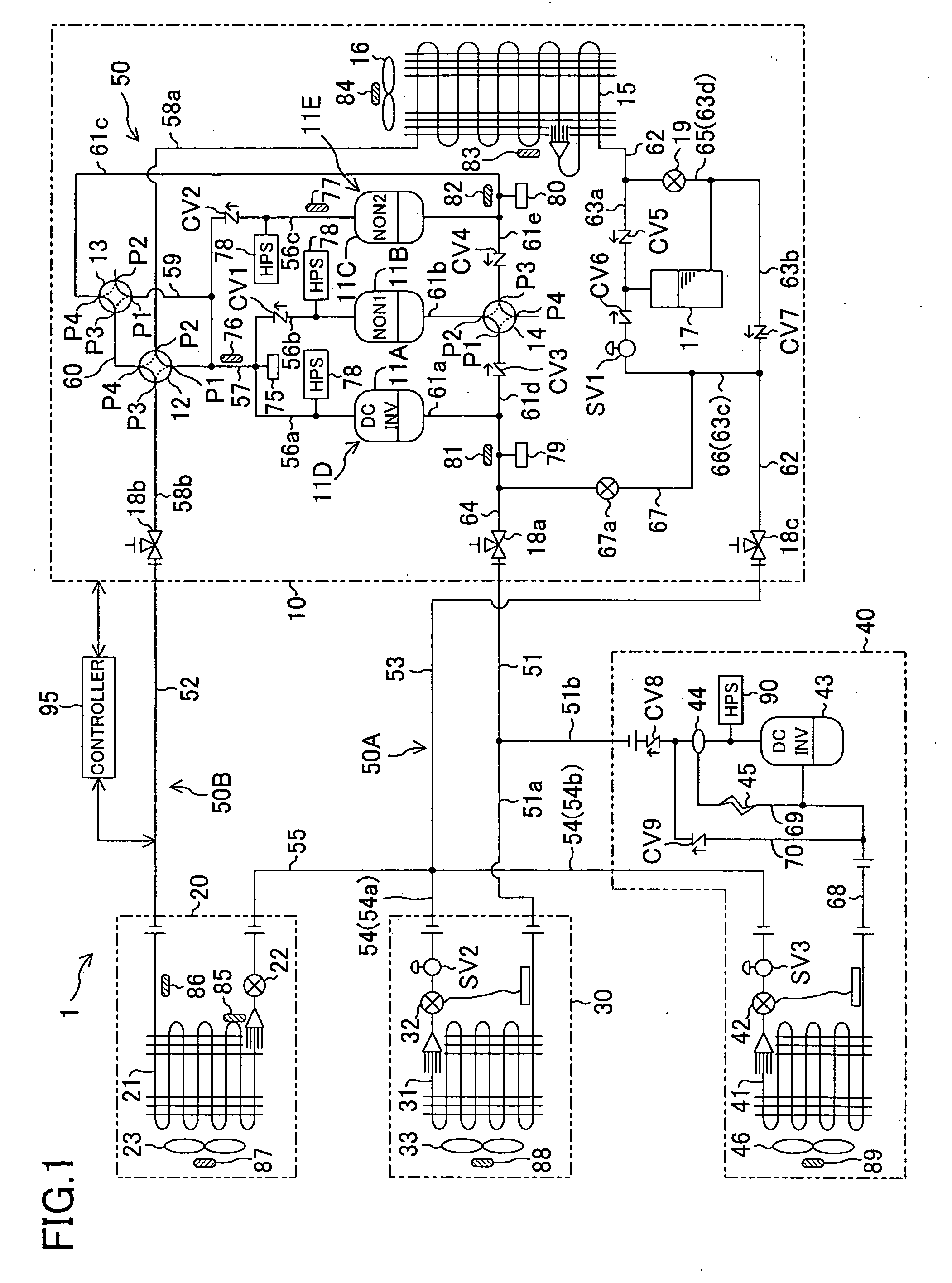
evaporator, the liquid refrigerant inflow passageway (66) is connected to the heat source-side liquid pipe (62) of the heat source-side unit (10), the heat source-side liquid pipe (62) being connected to the integrated liquid pipe (53) of the liquid-side interunit piping line (53, 54, 55), and to the inlet port of the
receiver (17) and the switch valve (SV1) capable of being on-off controlled is disposed in the liquid refrigerant inflow passageway (66). Therefore, by performing such a 100% heat recovery
operation mode with the switch valve (SV1) placed in the
closed state, the refrigeration apparatus operates wherein the quantity of heat of condensation of the second utilization-side heat exchanger (21) and the quantity of heat of
evaporation of the first utilization-side heat exchanger (31, 41) are in balance with each other.
[0036]On the other hand, if the operation capacity of the compression mechanism (11D, 11E) is increased when there is excess refrigerant in the second utilization-side heat exchanger (21) and the liquid-side interunit piping line (53, 54, 55), an operation to place the switch valve (SV1) in the opened state is performed, thereby permitting escape of the liquid refrigerant accumulated in the second utilization-side heat exchanger (21) and the liquid-side interunit piping line (53, 54, 55) to the
receiver (17) from the first
branch liquid pipe (54) by way of the integrated liquid pipe (53), the heat source-side liquid pipe (62), and the liquid refrigerant inflow passageway (66). Therefore, it becomes possible to prevent the
high pressure of the compression mechanism (11D, 11E) from increasing too much. Accordingly, if it is arranged such that prior to activation of the
pressure switch (HPS) for
high pressure protection the switch valve (SV1) is placed in the opened state, this makes it possible to prevent the refrigeration apparatus from malfunctioning to stop operating due to shutdown of the compression mechanism (11D, 11E).
[0037]In the case where the second utilization-side units (20) are connected in parallel to the heat source-side unit (10), the
discharge pressure of the compression mechanism (11D, 11E) tends to increase if there is a second utilization-side unit (20) that is placed in the thermo-off state and in addition the refrigeration apparatus tends to stop operating because of activation of the
pressure switch for
high pressure protection. However, according to the second aspect of the present invention, placing the switch valve (SV1) in the opened state prior to activation of the
pressure switch may ensure that the malfunction of the refrigeration apparatus is prevented from occurring.
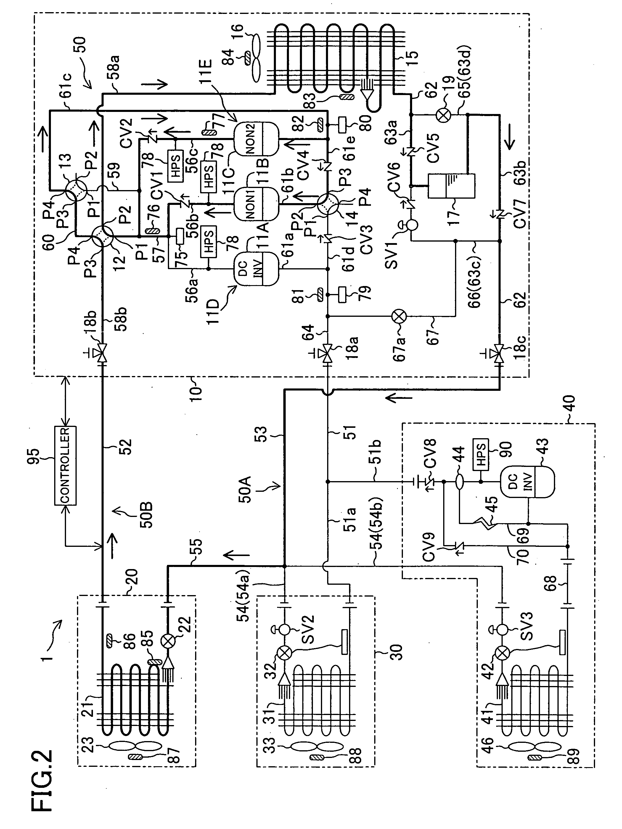
[0038]In the refrigeration apparatus according to the third aspect of the present invention having the first
system-side circuit (50A) in which refrigerant is circulated between the heat source-side unit (10) and the first utilization-side unit (30, 40) in one direction to thereby provide compartment cooling and the second
system-side circuit (50A) in which refrigerant is circulated reversibly between the heat source-side unit (10) and the second utilization-side unit (20) to thereby provide
indoor air conditioning, the
discharge pressure of the compression mechanism (11D, 11E) is prevented from increasing too much by placing the switch valve (SV1) in the opened state during the 100% heat recovery operation mode in which the second utilization-side heat exchanger (21) and the first utilization-side heat exchanger (31, 41) function, respectively, as a condenser and as an
evaporator, even if the operation capacity of the compression mechanism (11D, 11E) is increased when there is excess refrigerant in the second utilization-side heat exchanger (21) and the liquid-side interunit piping line (53, 54, 55). Accordingly, as in the first and second aspects of the present invention, it is ensured that the refrigeration apparatus is prevented from malfunction.
[0039]According to the fourth aspect of the present invention, by virtue of the provision of the control means (95) capable of on-off control of the switch valve (SV1) in response to the operation state, it becomes possible to prevent the occurrence of operation problems in the 100% heat recovery operation mode or other operation mode.
[0040]According to the fifth aspect of the present invention, in the operation state in which the second utilization-side heat exchanger (21) and the first utilization-side heat exchanger (31, 41) function, respectively, as a condenser and an
evaporator, the switch valve (SV1) is placed in the
closed state if the
discharge pressure of the compression mechanism (11D, 11E) is below the predetermined value while on the other hand the switch valve (SV1) is placed in the opened state if the
discharge pressure of the compression mechanism (11D, 11E) increases to equal or exceed the predetermined value. Therefore, during the 100% heat recovery operation mode, the switch valve (SV1) is placed in the
closed state under
normal conditions whereby the refrigeration apparatus operates wherein the quantity of heat of condensation of the second utilization-side heat exchanger (21) and the quantity of heat of
evaporation of the first utilization-side heat exchanger (31, 41) are in balance with each other. On the other hand, since it is possible to permit escape of high pressure refrigerant between the second utilization-side heat exchanger (21) and the liquid-side interunit piping line (53, 54, 55) into the receiver (17) by placing the switch valve (SV1) in the opened state if the
discharge pressure of the compression mechanism (11D, 11E) reaches the predetermined value or above, it becomes possible to prevent the problem that causes the refrigeration apparatus to stop operating by setting the set pressure of the switch valve (SV1) at which it is placed in the opened state to fall below the
working pressure of the pressure switch for high pressure protection.

