Dual beam heterodyne fourier domain optical coherence tomography

a fourier domain, heterodyne technology, applied in the field of fourier domain optical coherence tomography, can solve the problems of maximum depth ranging restrictions, signal degradation, distortion of mirror structures, etc., and achieve the effect of keeping beam scanning flexibility and without sacrificing measurement depth rang

Inactive Publication Date: 2010-06-10
ECOLE POLYTECHNIQUE FEDERALE DE LAUSANNE (EPFL)
View PDF1 Cites 11 Cited by
  • Summary
  • Abstract
  • Description
  • Claims
  • Application Information

AI Technical Summary

Benefits of technology

[0006]One objective of the present invention is to introduce a dual beam FDOCT variant that profits from the high phase stability of a common path configuration if used in conj

Problems solved by technology

Still, drawbacks of FDOCT are the depth dependent sensitivity as well as the complex ambiguity of the FDOCT signal leading to disturbing mirror structures as well as maximum depth ranging restrictions.
Any phase noise due to sample motion or mechanical beam scanning will cause signal degradation as well as insufficient suppression of mirror terms.
Another source of phase instabilities are fiber-based setups in case of employing handheld scanners where moving the sample arm fiber introduces unwanted phase changes.
However, not much flexibility is offered to the user since the reference re

Method used


Image

  • Dual beam heterodyne fourier domain optical coherence tomography
  • Dual beam heterodyne fourier domain optical coherence tomography
  • Dual beam heterodyne fourier domain optical coherence tomography

Examples


Embodiment Construction

Short Description of the Figures

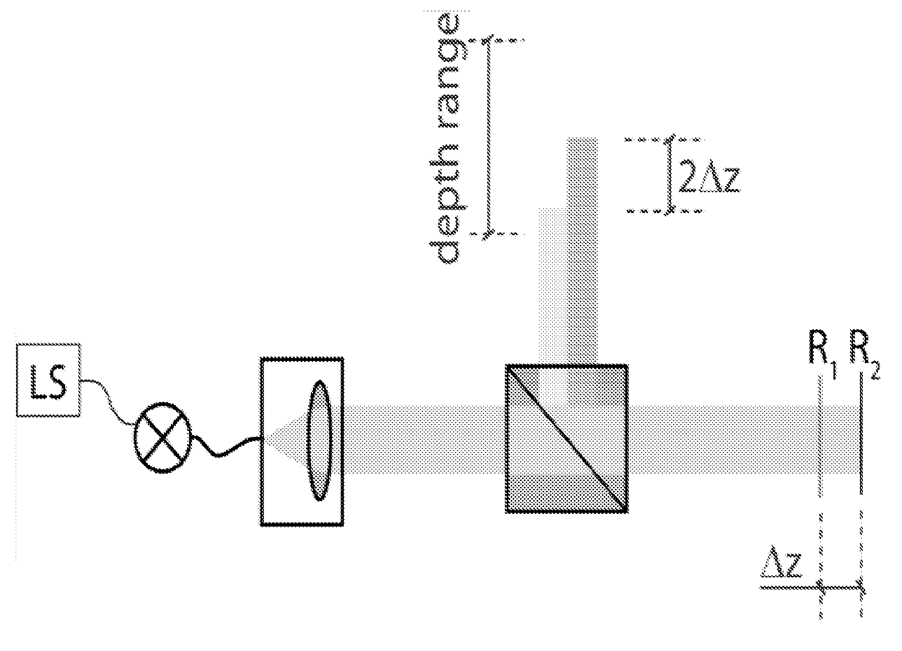
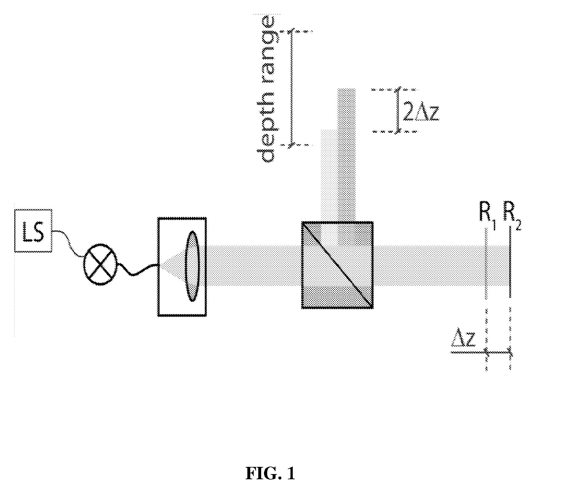
[0009]FIG. 1. Concept of a common path configuration. A prominent reflection (R1) close to the sample structure (R2) is used as reference signal. Δz is the optical path difference between the sample interfaces R1 and R2.

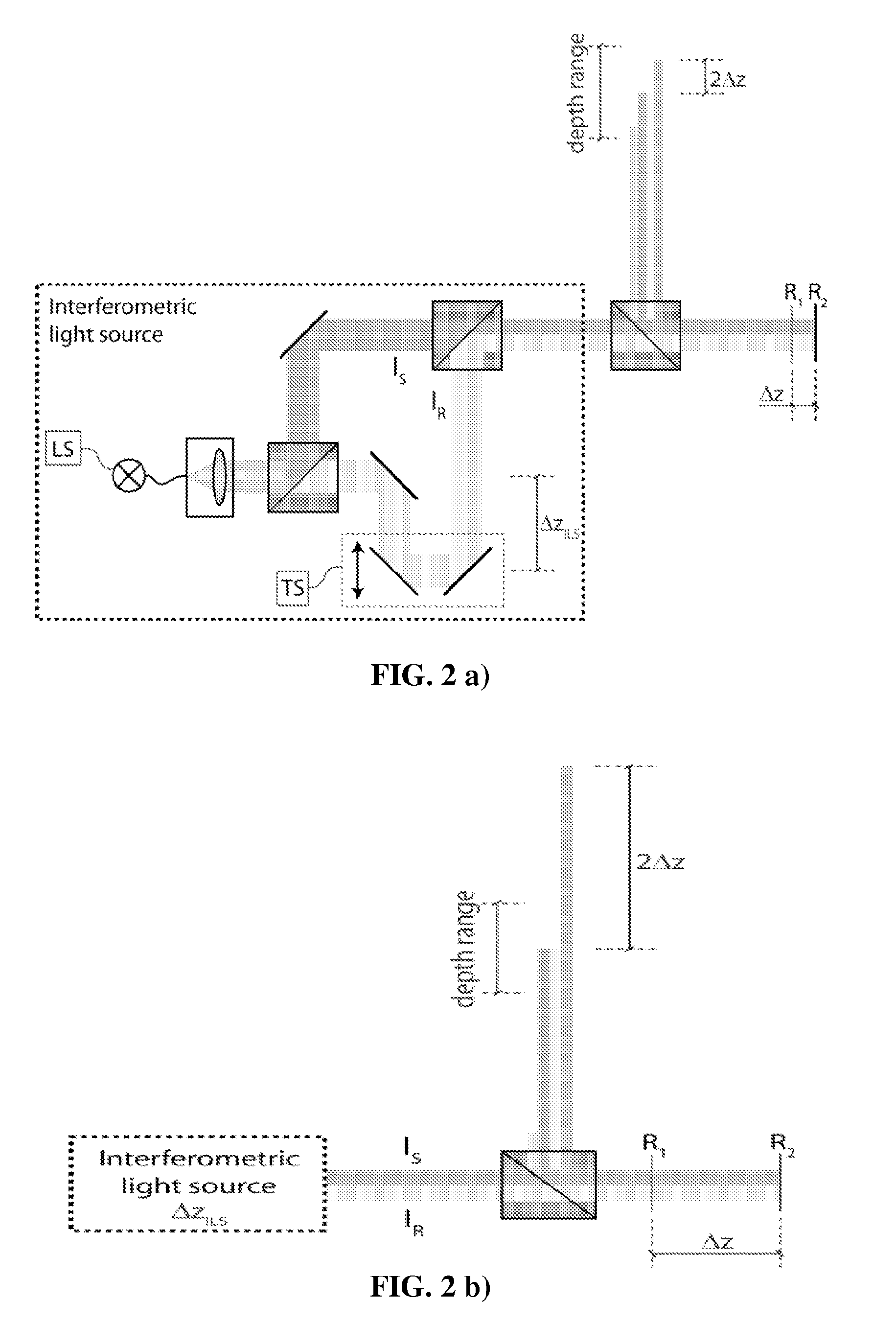
[0010]FIG. 2. (a) Dual beam principle. The output of an interferometer with a relative delay of 2ΔzIILS between the two light beam intensities IR and IS (interferometric light source) is pre-compensating for the relative distance between R1 (reference surface) and R2 (sample). The configuration presents a small relative distance Δz between reference surface (R1) and sample (R2) and up to four cross correlation terms might occur. The blue beam can be considered as the reference beam. (b) Dual beam configuration presenting a large relative distance Δz as compared to the depth range of the spectrometer (or swept source respectively) and only one cross correlation term occurs.

[0011]FIG. 3. Scheme illustrating the filling of a camera pixel ...


PUM


Abstract

The present invention relates to an apparatus and a method combining achromatic complex FDOCT signal reconstruction with a common path and dual beam configuration. The complex signal reconstruction allows resolving the complex ambiguity of the Fourier transform and to enhance the achievable depth range by a factor of two. The dual beam configuration shares the property of high phase stability with common path FDOCT. This is of importance for a proper complex signal reconstruction and is in particular useful in combination with handheld probes such as in endoscopy and catheter applications. The advantages of the present invention are in particular the flexibility to choose arbitrarily positioned interfaces in the sample arm as reference together with the possibility to compensate for dispersion.

Description

FIELD OF INVENTION[0001]The present invention relates to Fourier Domain Optical Coherence Tomography, commonly named FDOCT.STATE OF THE ART[0002]FDOCT has nowadays reached large acceptance in the biomedical imaging community due to the sensitivity advantage together with the possibility of high resolution imaging at high acquisition speed [1-7]. Recent realizations based on swept source technology achieve unprecedented scan speeds of several 100kHz with high phase accuracy [8-10]. Still, drawbacks of FDOCT are the depth dependent sensitivity as well as the complex ambiguity of the FDOCT signal leading to disturbing mirror structures as well as maximum depth ranging restrictions. A potential candidate to remove those artifacts is heterodyne FDOCT, both for the spectrometer-based [11] as well as for the swept source modality [12-14].[0003]Nevertheless, in particular spectrometer-based FDOCT needs high phase stability between successive spectra. Any phase noise due to sample motion or ...

Claims


Application Information

Patent Timeline
IPC IPC(8): G01B9/02
CPCG01N21/4795G01B9/02079G01B9/02003G01B2290/70G01B9/02057G01B9/02091G01B9/02069G01B9/02044
Inventor LEITGEB, RAINERVILLIGER, MARTINMICHAEY, ROLANDLASSER, THEOBACHMANN, ADRIAN
Owner ECOLE POLYTECHNIQUE FEDERALE DE LAUSANNE (EPFL)
Why Eureka
Try Eureka