Method for manufacturing magnetoresistance effect element using simultaneous sputtering of Zn and ZnO

Active Publication Date: 2010-06-10
TDK CORPARATION
View PDF9 Cites 1 Cited by
  • Summary
  • Abstract
  • Description
  • Claims
  • Application Information

AI Technical Summary

Benefits of technology

[0015]It is known that a ZnO film shows extremely strong polarity. Therefore, in a film forming method, a ZnO film is formed with a c-axis orientation. C-axis orientation means that the c-axis is oriented in a direction perpendicular to a film surface of the ZnO film. In particular, it means that only either zinc elements or oxygen elements are formed on the outermost surface. These surfaces are respectively referred to as a zinc polarity surface and an oxygen polarity surface. However, which polarity surfaces appear on the outermost surface depends on a thickness of a ZnO film and other factors, that are difficult to control. One layer of the pair of the magnetic layers is formed on the ZnO film, and one layer of the pair is disposed on the ZnO film directly or via other metal layers. It is believed that inventor of the present application thinks that various properties of the MR effect element are affected by which polarity surface appears on the outermost surface, and this causes diversions of the MR rate and so on. In other words, it was inferred that an interfacial situation between the ZnO film and an adjacent layer formed directly on the film affects the pr

Problems solved by technology

However, which polarity surfaces appear on the outermost surface depends on

Method used


Image

  • Method for manufacturing magnetoresistance effect element using simultaneous sputtering of Zn and ZnO
  • Method for manufacturing magnetoresistance effect element using simultaneous sputtering of Zn and ZnO
  • Method for manufacturing magnetoresistance effect element using simultaneous sputtering of Zn and ZnO

Examples


first embodiment

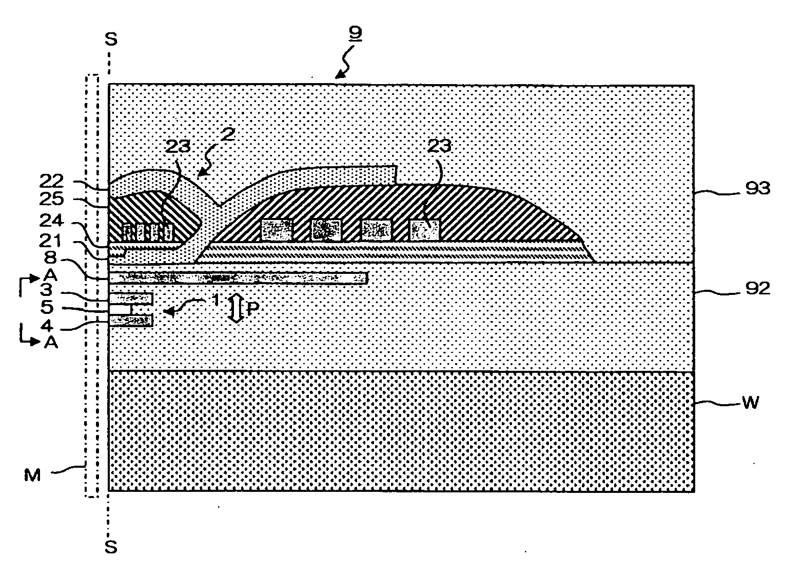
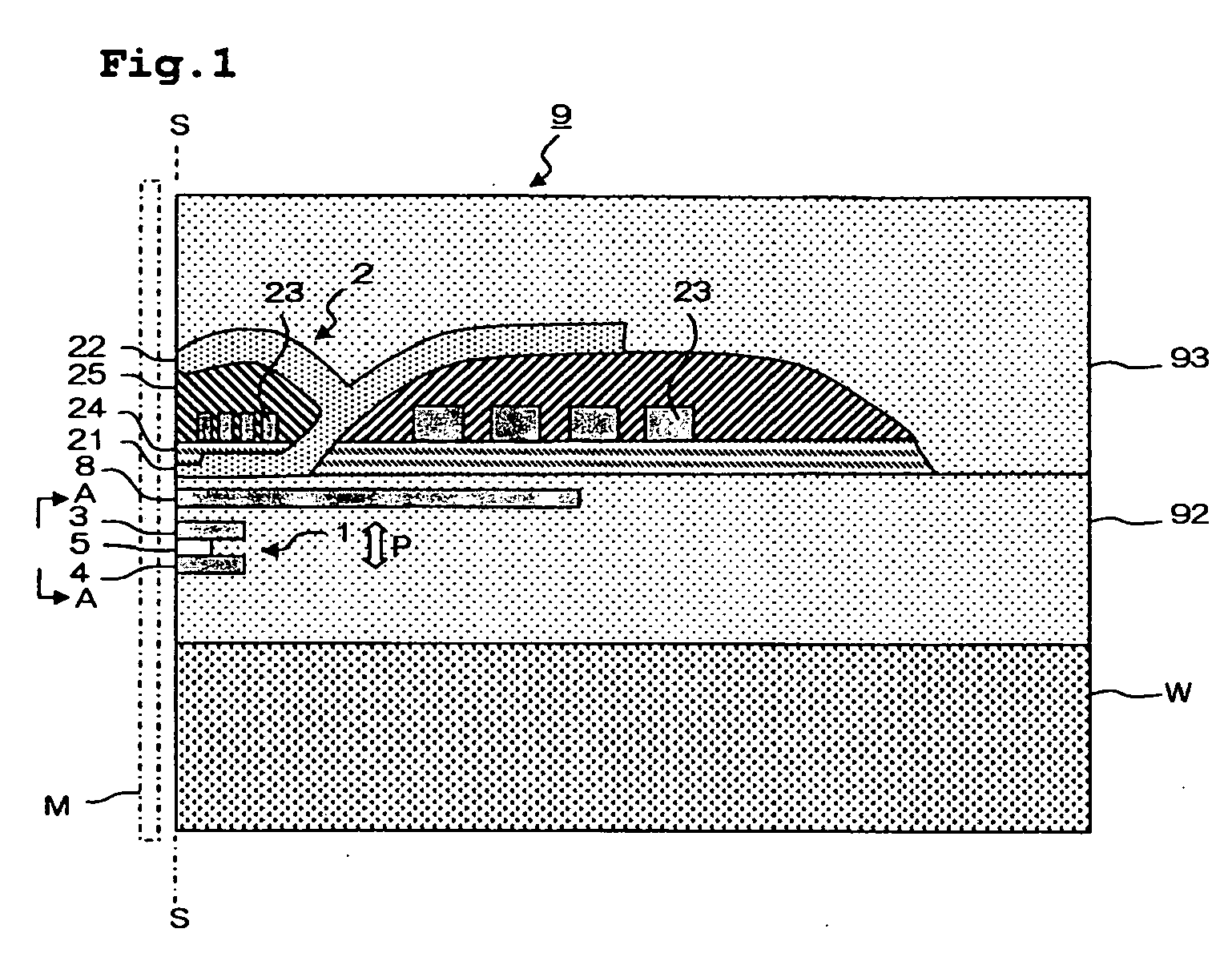
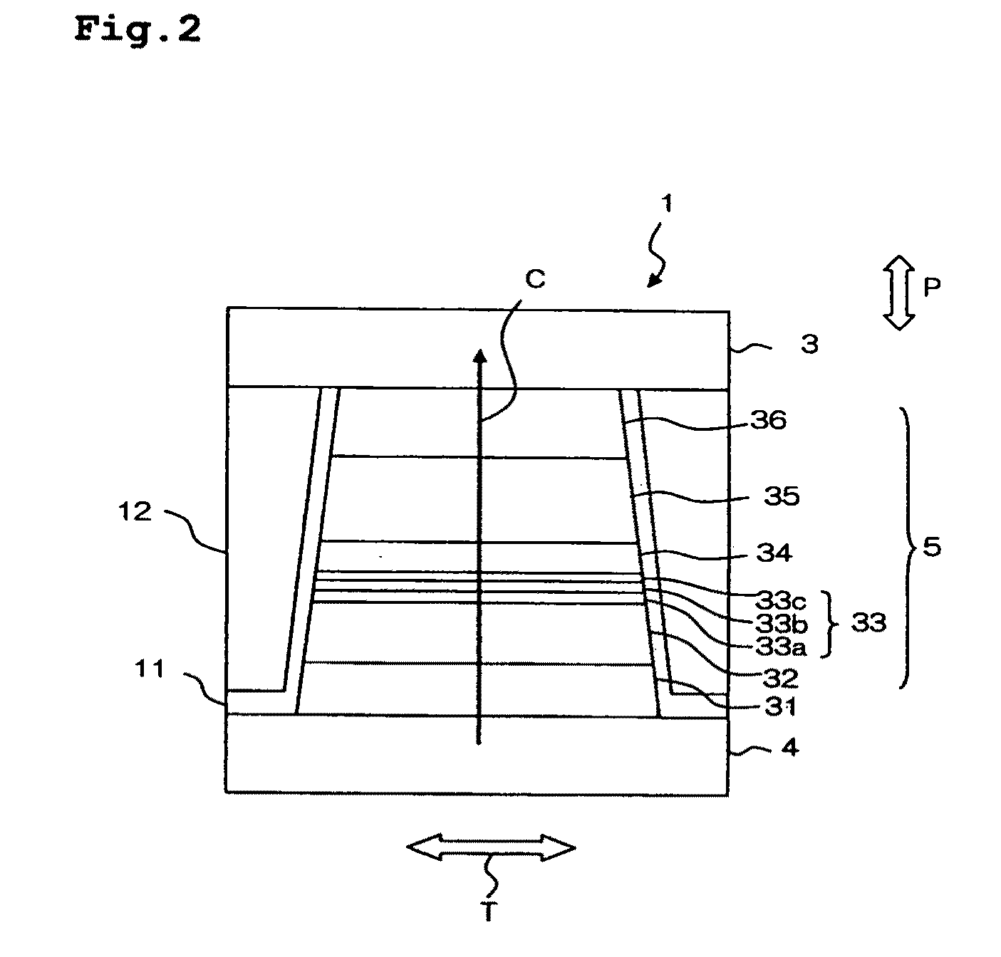
[0032]FIG. 1 is a main part sectional view of such a thin film magnetic head. FIG. 2 is a side view of the MR effect element viewed from a direction of A-A of FIG. 1; that is, the ABS S. The ABS S is a surface on which a thin film magnetic head 9 faces a recording medium M.

[0033]The thin film magnetic head 9 has an MR effect element 1 forming a reading head, and a writing head 2, both of which are formed above a substrate W. Referring to FIG. 2, the MR effect element 1 has a magneto-resistive (MR) layered body 5 in which many layers are deposited, an upper shield electrode layer 3 and a lower shield electrode layer 4 that are formed in a manner of sandwiching the MR layered body 5 in a perpendicular direction relative to the film surfaces (layering direction) P. A tip section of the MR layered body 5, as shown in FIG. 1, is disposed on the ABS S in an exposed state. The MR layered body 5 is configured to run a sense current in the film surface perpendicular direction P due to a volt...

second embodiment

[0044]FIG. 3 is a perspective view of a main section of the MR effect element 1 a viewed from a side of the ABS of the thin film head of the present embodiment. FIG. 4 is a partially enlarged perspective view of FIG. 3. The thin film magnetic head of the present embodiment is the same as the first embodiment shown in FIG. 1 except for a configuration of the MR effect element. The MR effect element 1a has the MR layered body 15 in which many layers are deposited as in the first embodiment, with the upper shield electrode layer 3a and the lower shield electrode layer 4a formed in a manner of sandwiching the MR layered body 15 in the perpendicular direction (layering direction) P relative to a film surface. Table 2 shows one example of a film configuration of the MR layered body 15. Table 2 shows layers from the exchange coupling transmitting layer 51 adjoining the lower shield electrode layer 4a toward the exchange coupling transmitting layer 59 adjoining the upper shield electrode la...

example 1

[0067]It is assured that a thin film having a flat surface of ZnO is formed and the c-axis orientation ((002) orientation) can be restrained by using the new technique of sputtering ZnO and Zn simultaneously in a mix gas of argon and oxygen, described above.

[0068]In the example, ZnO whose oxygen is deficit (or lost) is made by distributive adjustment of application power at a simultaneous sputtering. However, a similar effect is expected when in a composition of targets using for sputtering, another composition adjusted to a side of deficient oxygen is used.

[0069]A sample used for the evaluation is made by the processes below:[0070](1) One layer film of ZnO whose thickness is 50 mm (see FIG. 3 for detailed conditions of forming a film) is formed on a thermally-oxidized Si substrate.[0071](2) Heat treatment is carried out at 250° C. for 3 hours after forming the film, and samples 01-24 are made.

[0072]Table 3 shows film forming conditions of ZnO in example 1 and a percentage of oxygen...


PUM

PropertyMeasurementUnit
Fractionaaaaaaaaaa
Fractionaaaaaaaaaa
Pressureaaaaaaaaaa

Abstract

A method of manufacturing a magnetoresistive (MR) effective element having a pair of magnetic layers and a nonmagnetic intermediate layer including a ZnO film, wherein a relative angle of magnetization directions of the pair of magnetic layers varies according to an external magnetic field. The method includes a step for introducing a mix gas of oxygen gas and argon gas into a depressurized chamber, wherein a first target of ZnO, a second target of Zn and a substrate having a right-below layer are disposed in the chamber, and a step for depositing the ZnO film on the right-below layer by applying each of a first and second direct current (DC) application power to spaces between the first and second targets and the substrate respectively after the mix gas introducing step, wherein the first and second targets are set at negative potential, and the substrate is set at positive potential.

Description

BACKGROUND OF THE INVENTION[0001]1. Field of the Invention[0002]The present invention is related to a method for manufacturing a magnetoresistive (MR) effect element and to the MR effect element manufactured by the method. Also, the present invention is related to a method for forming a zinc oxide (ZnO) film.[0003]2. Description of the Related Art[0004]Zinc oxide (ZnO) is an important material that is used in various fields. For example, ZnO has been widely used in cosmetics to take advantage of its ultraviolet ray absorbing function, as a vulcanization accelerator of rubber, and in electric components such as a gas sensor and a varistor. In recent years, it has attracted attention as a transparent electrode film as an alternative to Sn doping In2O3 (ITO). As a transparent electrode film, ZnO has been already used for a white light emitting diode, a touch panel, a thin-type display device and a solar battery, and its use has been rapidly increasing. Furthermore, it is discussed that...

Claims


Application Information

Patent Timeline
IPC IPC(8): G11B5/33B05D5/12
CPCB82Y25/00C23C14/0036G11B5/3912G01R33/093C23C14/3464
Inventor HARA, SHINJITSUCHIYA, YOSHIHIROCHOU, TSUTOMUMIZUNO, TOMIHITO
Owner TDK CORPARATION
Why Eureka
Try Eureka