
Lithium secondary battery, secondary battery module, and secondary battery pack

a secondary battery and battery module technology, applied in the direction of secondary cell servicing/maintenance, cell components, sustainable manufacturing/processing, etc., can solve the problems of complex manufacturing process and battery structure, reduced yield, and complicated manufacturing process, so as to reduce resistance, reduce electrical resistance, and increase output power

Inactive Publication Date: 2010-06-10
HITACHI VEHICLE ENERGY
View PDF5 Cites 59 Cited by
  • Summary
  • Abstract
  • Description
  • Claims
  • Application Information

AI Technical Summary

Benefits of technology

[0007]In the technique described in JP-A-2000-77055, the manufacturing process is complicated since installing the plurality of current collector tabs and alignment of the tabs are necessary, although an internal resistance of the battery case be reduced by using the plurality of current collector tabs. In other words, a plurality of current collector tabs can be led out to the wound electrode body formed by winding the cathode and the anode in principle. However, due to variations of the thicknesses of the cathode and the anode and the limitation of accuracy of the winding, the manufacturing process and the battery structure may be complex, and the yield may be reduced. In the structure of the arrayed cylindrical secondary batteries disclosed in JP-A-2003-533844, the ratio of parts such as a battery can to the secondary battery modules is large, resulting in reduced gravimetric energy density. It can be expected that a reduction in a resistance of a battery having a simple structure results in an increase in the output of a lithium secondary battery. It can also be expected that the reduction in the resistance leads to increases in the outputs of a secondary battery module and a secondary battery pack.
[0008]It is, therefore, an object of the present invention to provide a lithium secondary battery having high output power, a secondary battery module having a plurality of the lithium secondary batteries, and a secondary battery pack having a plurality of the secondary battery modules.
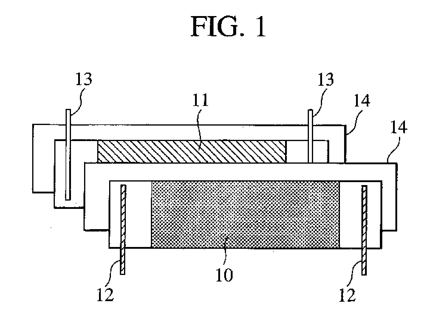
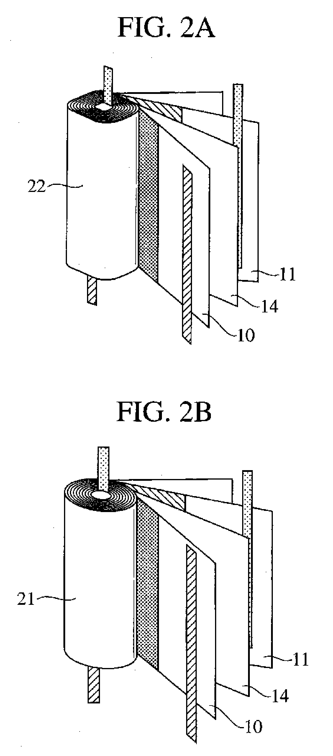
[0023]According to the aspect, at least one elongated cathode conducting member protrudes from each of the end portions (of the cathode) located on both end sides of the cathode, and at least one elongated anode conducting member protrude from each of the end portions (of the anode) located on both end sides of the anode. Each of the cathode conducting member and the anode conducting member has a cross sectional area of 0.4 mm2 or less. Thus, the lithium secondary battery has a reduced electrical resistance and improved output power. In addition, each of the wound electrode bodies has a capacity of 1.5 Ah or less. Thus, a current flowing in the cathode is evenly distributed, and a current flowing in the anode is evenly distributed. In addition, the lithium secondary battery has a reduced resistance.
[0027]According to the present invention, at least one elongated cathode conducting member protrudes from each of the end portions (non-deposition portions) located on both end sides of the cathode, and at least one elongated anode conducting member protrudes from each of the end portions (non-deposition portions) located on both end sides of the anode. Each of the cathode conducting members and the anode conducting members has a cross sectional area of 0.4 mm2 or less. Thus, the lithium secondary battery has a reduced electrical resistance and increased output power. Each of the wound electrode bodies has a capacity of 1.5 Ah or less. Thus, a current flowing in the cathode and the anode of each of the wound electrode bodies is evenly distributed. In addition, the lithium secondary battery has a reduced resistance.

Problems solved by technology

In the technique described in JP-A-2000-77055, the manufacturing process is complicated since installing the plurality of current collector tabs and alignment of the tabs are necessary, although an internal resistance of the battery case be reduced by using the plurality of current collector tabs.
However, due to variations of the thicknesses of the cathode and the anode and the limitation of accuracy of the winding, the manufacturing process and the battery structure may be complex, and the yield may be reduced.

Method used


Image

  • Lithium secondary battery, secondary battery module, and secondary battery pack
  • Lithium secondary battery, secondary battery module, and secondary battery pack
  • Lithium secondary battery, secondary battery module, and secondary battery pack

Examples


examples

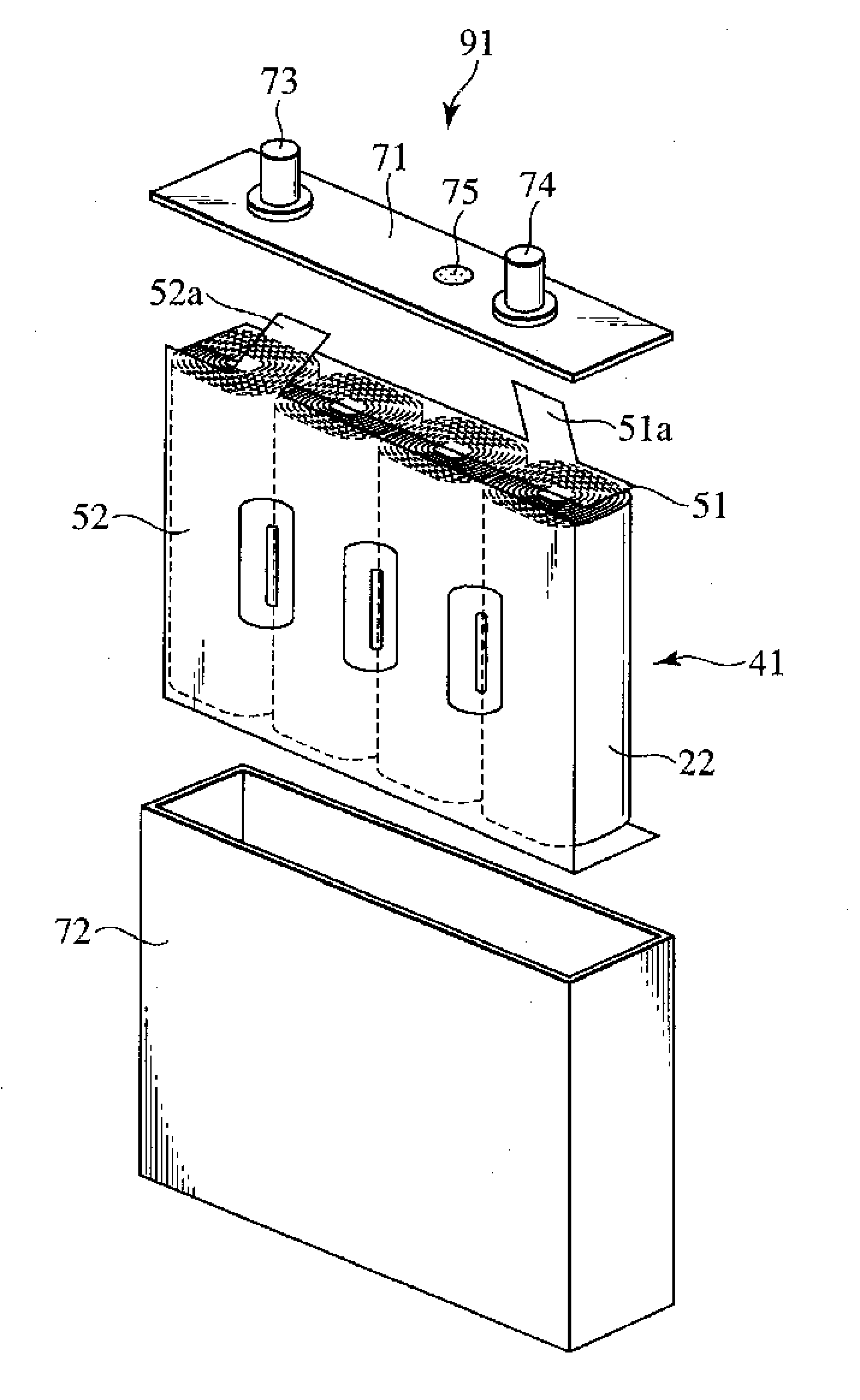
[0086]The following describes examples of the lithium secondary battery 91, the lithium secondary battery module 112 and the lithium secondary battery pack 121, which are formed according to the present embodiment. The present invention, however, is not limited to the examples. The first and second examples describe the lithium secondary battery 91. The third example describes the lithium secondary battery module 112. The fourth example describes the lithium secondary battery pack 121. In addition, another lithium secondary battery is described as a comparative example below.

first example

Formation of Cathode

[0087]A nickel oxide, a manganese oxide and a cobalt oxide are used as materials of the cathode active material in the first example. Those oxides are prepared to ensure that atom ratios of Ni, Mn and Co are 1:1:1. The three types of oxides are pulverized and mixed by a wet pulverizer. Polyvinyl alcohol (PVA) is added to the pulverized and mixed material (oxides). The thus-obtained powder is granulated by a spray dryer. The granulated powder is introduced into a high-purity alumina container. Then, the powder is temporarily fired at a temperature of 600° C. for 12 hours to evaporate the PVA. The powder is then cooled. After the cooling, the powder is disintegrated. Then, lithium hydroxide monohydrate is added to and sufficiently mixed with the disintegrated powder to ensure that atom ratios of Ni, Mn and Co (transition metals) are 1:1:1. The mixed powder is introduced into a high-purity alumina container and fired at a temperature of 900° C. for 6 hours to obtain...

second example

[0095]In the second example, wound electrode bodies each having a capacity of 1.0 Ah, wound electrode bodies each having a capacity of 1.2 Ah, and wound electrode bodies each having capacity of 2.0 Ah are formed in the same way as the first example. The cross sectional areas of the cathode tab 12 and the anode tab 13 of each of the wound electrode bodies are in a range of 0.3 mm2 to 0.4 mm2. Six wound electrode bodies having capacities of 1.0 Ah are connected in parallel. Five wound electrode bodies having capacities of 1.2 Ah are connected in parallel. Three wound electrode bodies having capacities of 2.0 Ah are connected in parallel. The aforementioned pulse charging / discharging test was carried out on each of lithium secondary batteries, which are a lithium secondary battery having the wound electrode bodies each having a capacity of 1.0 Ah, a lithium secondary battery having the wound electrode bodies each having capacity of 1.2 Ah and a lithium secondary battery having the woun...


PUM


Abstract

A lithium secondary battery having improved output power includes a plurality of wound electrode bodies in a battery can. Each wound electrode body is formed by winding a cathode and an anode with a separator placed the separator between the cathode and the anode. Each of the wound electrode bodies has a capacity of 1.5 Ah or less. The cathode includes a cathode current collector foil and cathode materials. End portions of the cathode are located on two end sides of the cathode current collector foil and include shorter sides of the cathode current collector foil, respectively. The active portion of the cathode has a cathode mixture deposited thereon and is sandwiched between the end portions. Cathode tabs extend from the end portions of the cathode current collector foil. The anode includes an anode current collector foil and anode materials, where both edges do not have an anode mixture.

Description

BACKGROUND OF THE INVENTION[0001]1. Field of the Invention[0002]The present invention relates to a lithium secondary battery, a secondary battery module, and a secondary battery pack. More particularly the invention relates to a lithium secondary battery which includes a wound electrode body that is formed by winding a cathode and an anode with a separator placed between the cathode and the anode and a battery case housing the wound electrode body, a secondary battery module having a plurality of the lithium secondary batteries, and a secondary battery pack having a plurality of the secondary battery modules.[0003]2. Description of the Related Art[0004]Lithium secondary batteries are widely used as power supplies for computers, mobile phones, etc. since the lithium secondary batteries have high energy densities and high output densities. While electric vehicles and hybrid vehicles have been developed as environment-friendly vehicles, lithium secondary batteries have been considered ...

Claims


Application Information

Patent Timeline
IPC IPC(8): H01M6/10H01M10/052H01M10/0566H01M10/0587H01M10/60H01M10/613H01M10/617H01M10/625H01M10/647H01M10/6555H01M10/6557H01M10/6563H01M50/209H01M50/503H01M50/516H01M50/522H01M50/534H01M50/536H01M50/538
CPCH01M2/1022H01M2/1077H01M2/206H01M2/263H01M6/42Y02T10/7011H01M10/0587H01M10/425H01M2010/4292Y02E60/122H01M10/052Y02E60/10H01M50/538Y02P70/50H01M50/503H01M50/536H01M50/209H01M50/522H01M50/534H01M50/516Y02T10/70
Inventor HONBOU, HIDETOSHI
Owner HITACHI VEHICLE ENERGY
Learn More