Gas turbine with water injection

a gas turbine and water injection technology, applied in steam engine plants, combustion processes, lighting and heating apparatus, etc., can solve problems such as flashback, increased nox emissions, and hydrogen in conventional combustion systems of gas turbines

Active Publication Date: 2010-06-17
ANSALDO ENERGIA SWITZERLAND AG
View PDF12 Cites 28 Cited by
  • Summary
  • Abstract
  • Description
  • Claims
  • Application Information

AI Technical Summary

Benefits of technology

[0014]One of numerous aspect of the present invention includes the reliable, low-NOx combustion of hydrogen-rich fuel gases in the gas turbines. In particular, the safeguarding against flashback when combusting hydrogen-rich fuel gases in gas turbines is another of these aspects.

Problems solved by technology

On the other hand, the limited natural gas reserves lead to considerations of using synthetically processed gaseous fuels alternatively to, or in combination with, the combustion of conventional types of fuel.
The combustion of hydrogen in conventional combustion systems of gas turbines leads to technical problems, as is known, such as increased NOx emissions and flashback, on account of the high flame velocity and short ignition delay times of the hydrogen.
This high flame velocity in the case of rich mixture, without suitable countermeasures in a gas turbine, leads to ignition and flashback of the air-fuel mixtures directly after injection of the hydrogen-rich fuel.
The flame in this case flashes back into the burners in an uncontrolled manner and, as a result of the locally high fuel concentrations, very large temperature spikes, with correspondingly heavy NOx emission, occur.
As a result of the flashback, the burner hardware can also be damaged within a shorter time.
Large secondary drops lead only to a limited extent to the desired local cooling in the fuel-air mixture and guarantee the risk of thermal shocks if they reach hot parts.

Method used


Image

  • Gas turbine with water injection
  • Gas turbine with water injection
  • Gas turbine with water injection

Examples


Embodiment Construction

[0052]A gas turbine with a device for carrying out a method embodying principles of the present invention essentially has at least one compressor, at least one combustion chamber, and at least one turbine which, via at least one shaft, drives the compressor and a generator.

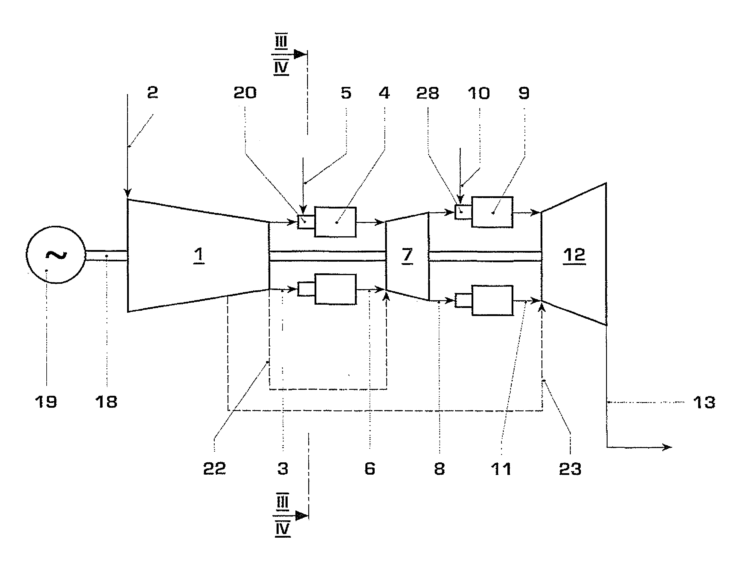
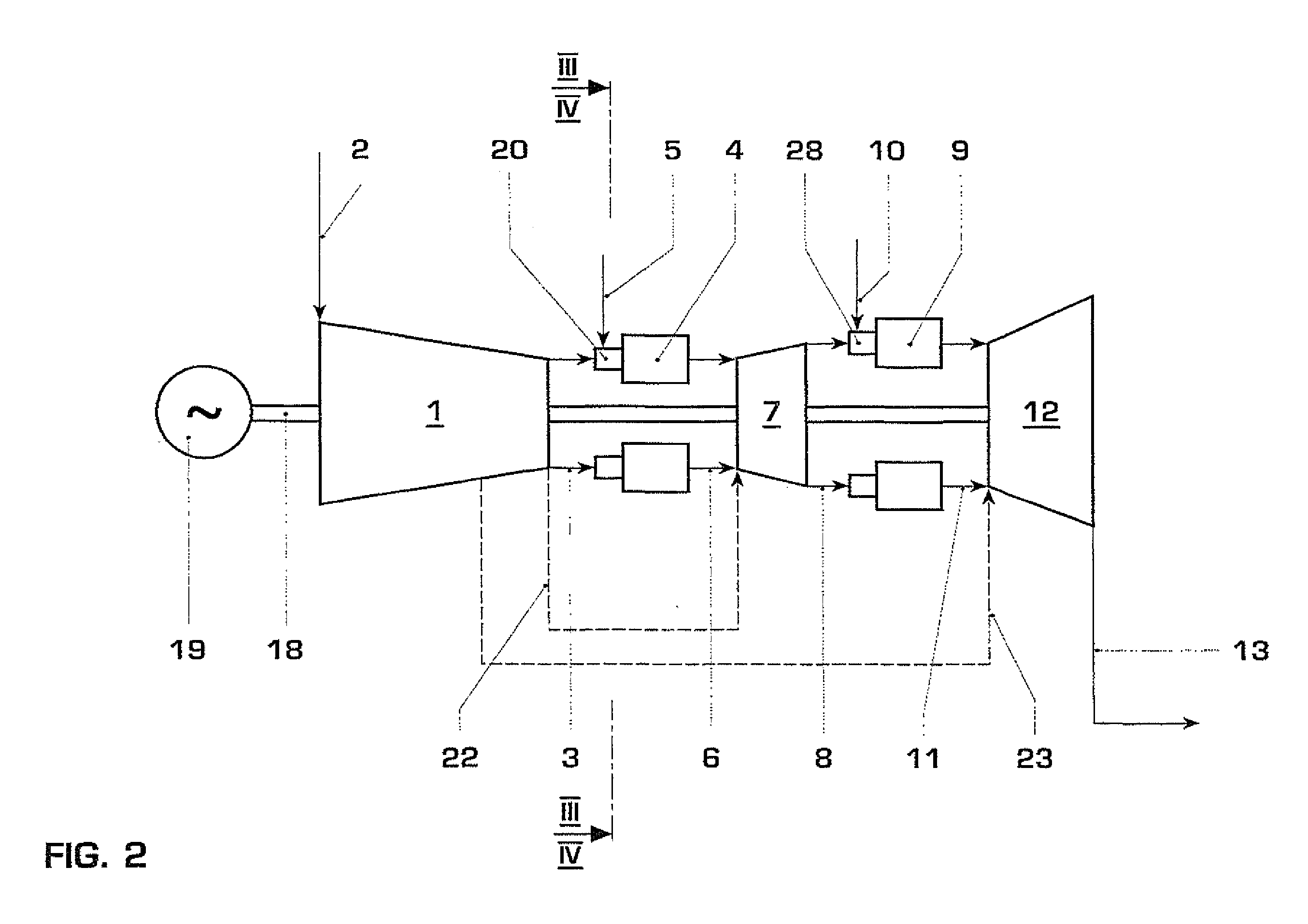
[0053]FIG. 2 for example shows a gas turbine plant with sequential combustion, which, in an as known per se manner, also includes a compressor 1, a first combustion chamber 4, a first turbine 7, a second combustion chamber 9, a second turbine 12, and also a generator. The turbines 7 and 12, via a shaft 18, drive the compressor 1 and the generator 19.

[0054]The combustion chambers, for example, are constructed as annular combustion chambers with a multiplicity of individual burners 20, as is shown in FIGS. 3 and 4 based on the example of the first combustion chamber. Each of these burners is supplied with fuel gas via a fuel gas distribution system 24.

[0055]According to principles of the present invention, water is ...


PUM


Abstract

Reliable, low-NOx-emission operation of a gas turbine plant with hydrogen-rich fuel gas, and a gas turbine plant with a device for water injection into hydrogen-rich fuels in a gas turbine, involves suitable water injection (21), a water-fuel gas mist, i.e., a fuel gas in which fine water droplets are suspended, is created in the fuel gas feed line (15). This mist is introduced into the burners (20) of the gas turbine. As a result of the water-fuel gas mist, four effects are combined for ignition delay and reduction of the flame velocity of hydrogen-rich fuel gas. When using a water-fuel gas mist, the water, in a directed manner, reaches the region in the burner (20) in which it directly has the greatest possible effect upon the flame or the flame velocity.

Description

[0001]This application is a Continuation of, and claims priority under 35 U.S.C. §120 to, International patent application number PCT / EP2008 / 054718, filed 18 Apr. 2008, and claims priority therethrough under 35 U.S.C. §§119, 365 to European patent application number 07107730.9, filed 8 May 2007, the entireties of which are incorporated by reference herein.BACKGROUND[0002]1. Field of Endeavor[0003]The invention refers to a method for the reliable, low-NOx-emission operation of a stationary gas turbine plant with hydrogen-rich fuel gas, and also to a gas turbine plant with a device for carrying out the method.[0004]2. Brief Description of the Related Art[0005]The research and development of the combustion of hydrogen or hydrogen-rich fuels in gas turbines is essentially driven forward by two factors.[0006]On the one hand, there is a global interest in reducing the emission of greenhouse gases, especially of CO2. One possibility for this is the changeover from conventional fossil fuels...

Claims


Application Information

Patent Timeline
Patent Type & Authority Applications(United States)
IPC IPC(8): F02C3/30
CPCF01K21/047F01K23/067F02C3/30Y02E20/18F23K2401/10F23L7/002F23R3/28F23K5/007F23K2400/10
Inventor CARRONI, RICHARDGIUDATI, GIANFRANCO
Owner ANSALDO ENERGIA SWITZERLAND AG
Why Eureka
Try Eureka