System for Contactless Cleaning, Lithographic Apparatus and Device Manufacturing Method

a technology of lithographic equipment and manufacturing methods, applied in the field of contactless cleaning systems, lithographic equipment and device manufacturing methods, can solve problems such as substantial detriment to the quality of final products

Inactive Publication Date: 2010-06-17
THE BOARD OF TRUSTEES OF THE UNIV OF ILLINOIS +1
View PDF1 Cites 10 Cited by
  • Summary
  • Abstract
  • Description
  • Claims
  • Application Information

AI Technical Summary

Benefits of technology

[0010]The inventors have discovered a system for contactless removal of a particle from a surface of an object, including a source of plasma constructed to generate He plasma in a direct vicinity of the surface and a control unit constructed to modify plasma parameters to cause an increased generation of He metastables in the He plasma without affecting the source of plasma.
[0011]According to another aspect of the invention there is provided a lithographic projection apparatus provided with an optical system including optical elements to condition and / or supply a projection beam of EUV radiation and the system for contactless removal of a particle from a surface of an object, the system including a source of plasma constructed to generate He plasma in a direct vicinity of the surface and a control unit constructed to modify plasma parameters to cause an increased generation of He metastables in the He plasma without affecting the source of plasma.
[0012]According to still another aspect of the invention there is provided a device manufacturing method. The method includes providing a beam of EUV radiation using optical elements, projecting the beam onto a target portion of a layer of radiation-sensitive material, and cleaning a surface of at least one optical element using He plasma, wherein a population of He metastables in the He plasma is increased without affecting a source of He plasma.

Problems solved by technology

It is an intrinsic feature of an EUV lithographic technology that any contamination deposited on an optical element may cause a substantial detriment of final product quality.

Method used


Image

  • System for Contactless Cleaning, Lithographic Apparatus and Device Manufacturing Method
  • System for Contactless Cleaning, Lithographic Apparatus and Device Manufacturing Method
  • System for Contactless Cleaning, Lithographic Apparatus and Device Manufacturing Method

Examples


Embodiment Construction

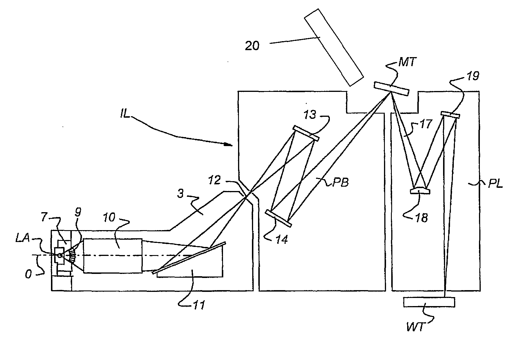
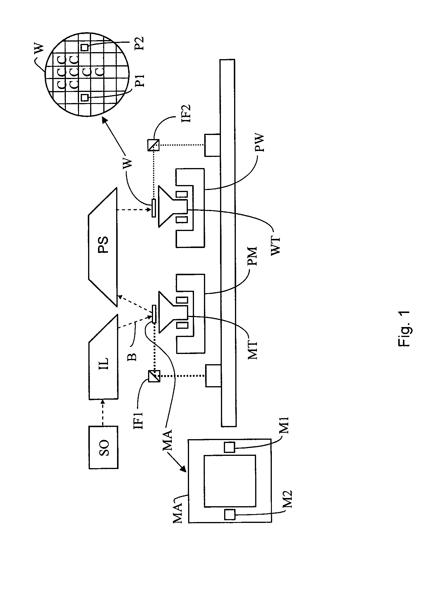
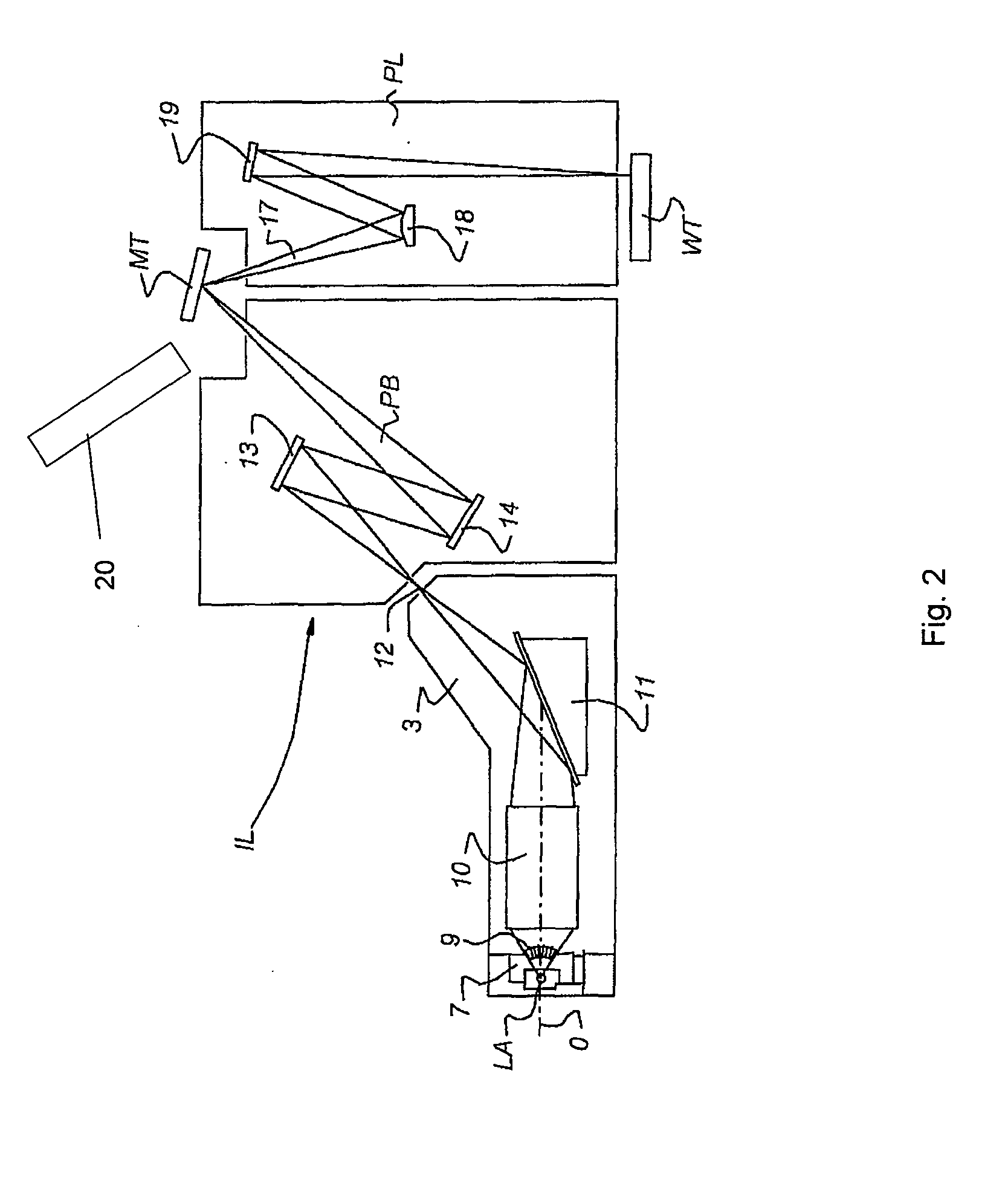
[0018]FIG. 1 schematically depicts a lithographic apparatus according to one embodiment of the invention. The apparatus includes:

[0019]an illumination system (illuminator) IL configured to condition a radiation beam B (e.g. EUV radiation).

[0020]a support structure (e.g. a mask table) MT constructed to support a patterning device (e.g. a mask) MA and connected to a first positioner PM configured to accurately position the patterning device in accordance with certain parameters;

[0021]a substrate table (e.g. a wafer table) WT constructed to hold a substrate (e.g. a resist-coated wafer) W and connected to a second positioner PW configured to accurately position the substrate in accordance with certain parameters; and

[0022]a projection system (e.g. a refractive projection lens system) PS configured to project a pattern imparted to radiation beam B by patterning device MA onto a target portion C (e.g. including one or more dies) of substrate W.

[0023]The illumination system may include var...


PUM

PropertyMeasurementUnit
Partial pressureaaaaaaaaaa
wavelengthaaaaaaaaaa
etch rateaaaaaaaaaa

Abstract

Embodiments of the invention relate to a system for contactless cleaning of an object surface, a lithographic apparatus including the system, and a method of manufacturing a device. The system may include a He plasma source contained in a chamber and a control unit constructed to modify plasma parameters in use, such as the electron energy distribution of the plasma for causing an increase in formation of He metastables without modifying operational parameters of the plasma source. The control unit may include an electrical biasing unit constructed to apply a positive bias voltage to the object, for attracting free electrons from the plasma. The system may include a supplementary gas source, which may be either pre-mixed with He or be supplied from a further gas source. The supplementary gas may be selected based on a pre-knowledge on a type of particles to be expected on the surface of the object.

Description

CROSS-REFERENCE TO RELATED APPLICATIONS[0001]The present application claims the benefit under 35 U.S.C §119(e) of U.S. Provisional Patent Application No. 61 / 100,957, filed Sep. 29, 2008, which is incorporated herein by reference in its entirety.BACKGROUND[0002]1. Field[0003]Embodiments of the present invention relate to a system for contactless removing of a particle from a surface of an object, a lithographic apparatus and a method for manufacturing a device using the same.[0004]2. Background[0005]A lithographic apparatus is a machine that applies a desired pattern onto a substrate, usually onto a target portion of the substrate. A lithographic apparatus can be used, for example, in the manufacture of integrated circuits (ICs). In that instance, a patterning device, which is alternatively referred to as a mask or a reticle, may be used to generate a circuit pattern to be formed on an individual layer of the IC. This pattern can be transferred onto a target portion (e.g. including p...

Claims


Application Information

Patent Timeline
Patent Type & Authority Applications(United States)
IPC IPC(8): G03F7/20G03B27/52B08B13/00
CPCG03F7/70925
Inventor SCACCABAROZZI, LUIGIBANINE, VADIM YEVGENYEVICHKOSTER, NORBERTUS BENEDICTUSMOORS, JOHANNES HUBERTUS JOSEPHINAVAN KAMPEN, MAARTENRAJU, RAMASAMYLYTLE, WAYNE MATHEWRUZIC, DAVID NEILNEUMANN, MARTIN JOHN
Owner THE BOARD OF TRUSTEES OF THE UNIV OF ILLINOIS
Why Eureka
Try Eureka