Retinal prosthetic devices

a prosthetic device and a technology for retinal prostheses, applied in the field of retinal prosthetic devices, can solve the problems of loss of photosensitivity, lack of known mechanism by which the eye can self-repair, and disappointing medical interventions to da

Inactive Publication Date: 2010-06-17
IMPERIAL INNOVATIONS LTD
View PDF5 Cites 23 Cited by
  • Summary
  • Abstract
  • Description
  • Claims
  • Application Information

AI Technical Summary

Problems solved by technology

These diseases result in the loss of photosensitivity primarily due to a lesion of the rod and cone photoreceptors, and medical intervention to date has been disappointing.
There is no known mechanism by which the eye can self-repair.
There are no drugs which can significantly slow the onset of most of these diseases, and none capable of restoring lost vision.
Stem cell therapies are complex and may be many decades away from potential treatment.
Both of these approaches are much more invasive.
There is also a much higher risk of problems due to infection or epileptic seizure.
However, the rigid silicon structures that have been implanted to date have their own problems.
The curved nature of the eye makes it very difficult to cover any significant portion of the retina, though there have been attempts at more flexible substrates.
Furthermore power consumption issues are highly significant to these devices.
Introduction of power cables is difficult, and power transmission through an RF link for example does not always provide sufficient power to power a significant quantity of stimulation points.
Furthermore the implant contains invasive electrodes used to inject current into ganglion cells, which can cause further degradation of remaining functional tissue.
Silicon substrates can be processed onto flexible structures, but they are fragile.
However, this technique is invasive, can damage the cells and hasten long term degradation processes of remaining retinal tissue.
Additionally, the position of the electrodes is fixed once they are inserted, and precise positioning on the micrometer scale is hard to control.
They achieved some limited success, but had no proposal to take this work beyond in-vitro.
There has however, been no realistic system proposed that could be used as a practical prosthetic device based upon optical stimulation.

Method used


Image

  • Retinal prosthetic devices
  • Retinal prosthetic devices
  • Retinal prosthetic devices

Examples


Embodiment Construction

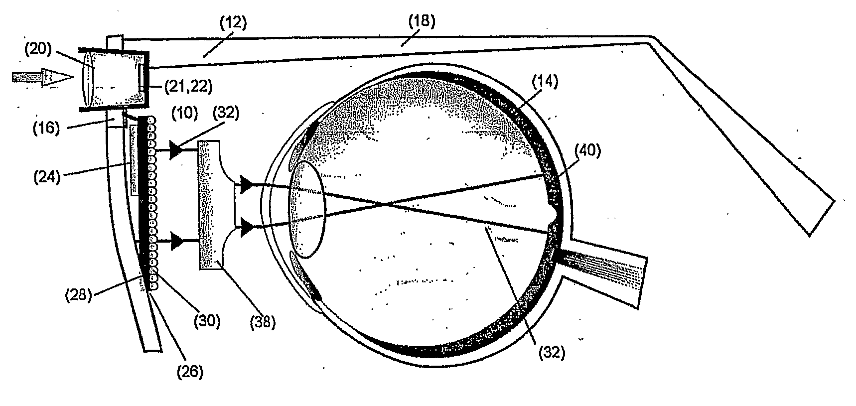
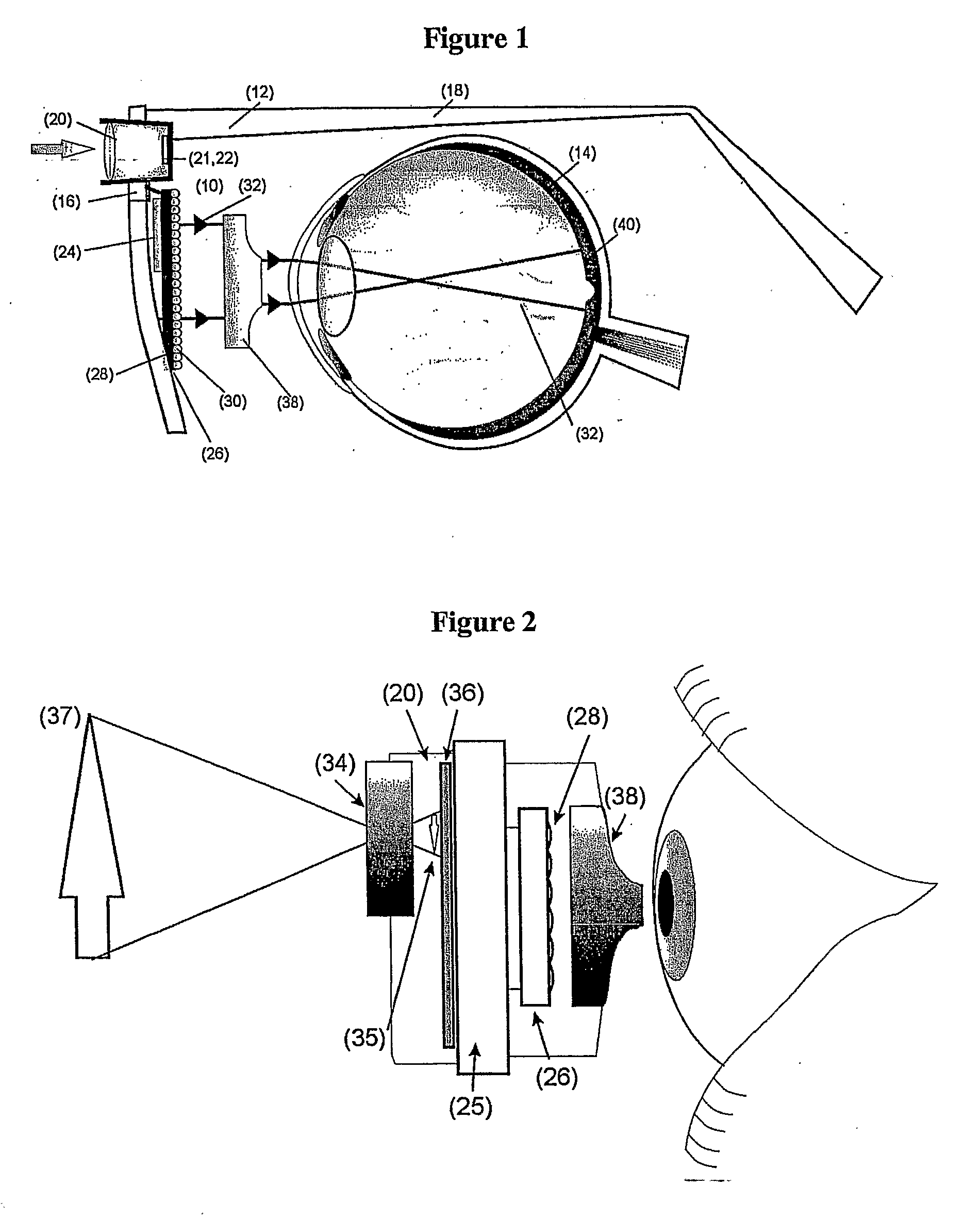
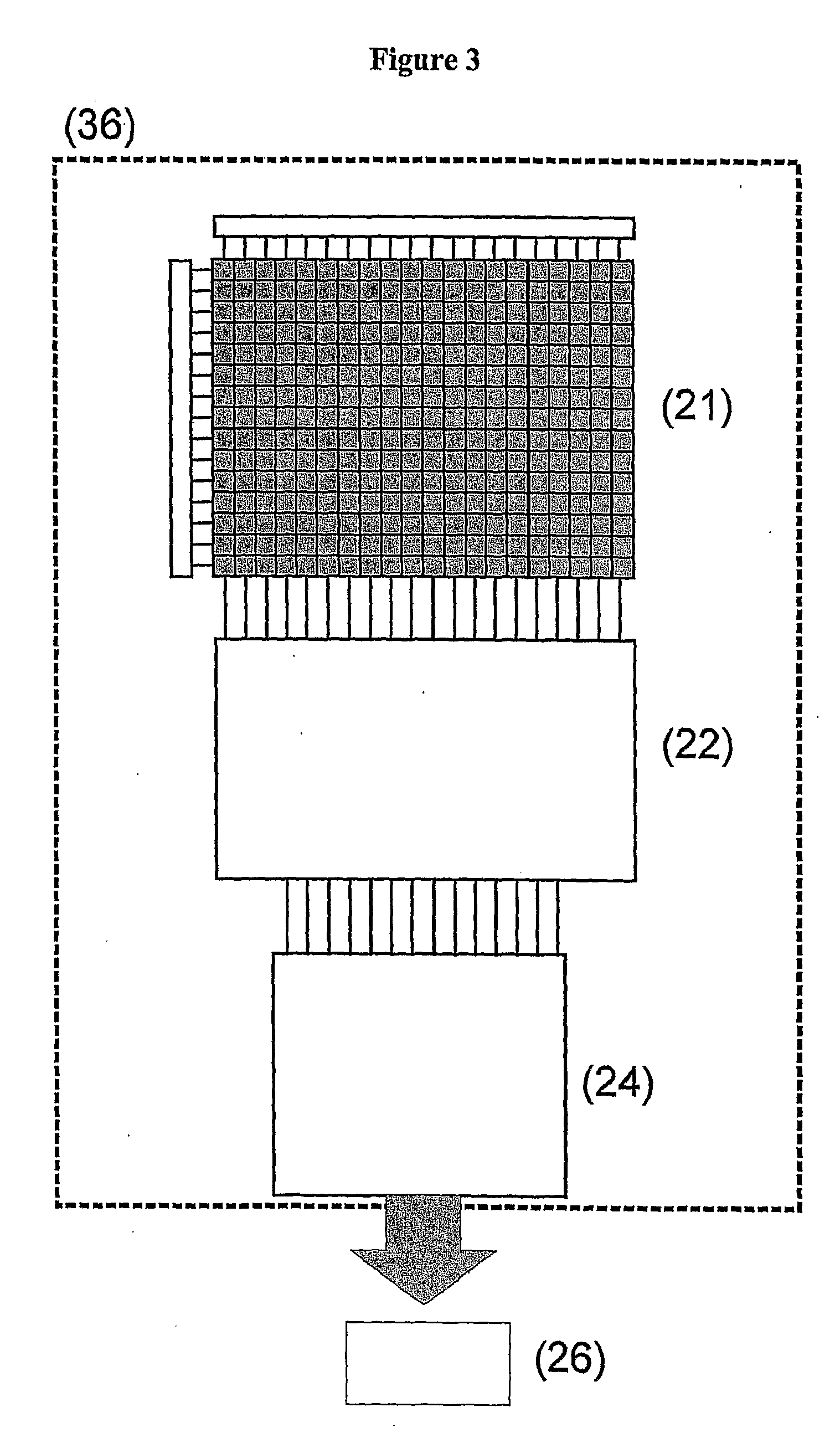
[0025]Referring to FIG. 1 a visual aid according to an embodiment of the invention comprises a retinal prosthetic device 10 mounted on a frame 12 which is arranged to support the device in front of a human eye 14. The frame is shaped in a similar manner to the frame of a pair of glasses and includes a bridge 16 arranged to rest on the bridge of the patient's nose and arms 18 arranged to be supported on the patient's ears. The prosthetic device 10 comprises in image capture system which includes a CMOS camera 20 and a processor 22 arranged to perform image processing functions. The device further comprises an LED stimulation addressing chip 24 and an array 26 of light sources in the form of LED devices 28 each of which can be turned on and off independently by the addressing chip 24. A lens 30 is located in front of each LED device 28 to focus the light that it emits into a focussed beam 32.

[0026]Referring to FIG. 2, which shows the prosthetic device 10 in a more schematic manner, th...


PUM


Abstract

A retinal prosthetic device comprises image capture means (20) arranged to capture an image, light producing means (30) arranged to define a plurality of light paths along each of which a light beam can be directed towards a respective position on a retina, and control means (24) arranged to process the captured image and control the light producing means so as to produce a stimulating array of light beams along a group of the light paths, the group being dependent upon the captured image.

Description

FIELD OF THE INVENTION[0001]The present invention relates to retinal prosthetic devices, and to the use of such devices to overcome partial or complete loss of vision.BACKGROUND TO THE INVENTION[0002]About 0.8% of Americans and Europeans older than 40 years are blind according to the US definition of blindness (<20 / 200 best corrected visual acuity in the better-seeing eye). About 0.04% of the population suffer low vision and blindness due to retinal dystrophies classed collectively as retinitis pigmentosa. A further 1-2 percent of over 50′s and 25% of over 80's suffer from reduced vision due to age related macular degeneration (AMD). AMD increases dramatically with age, so that (with about 2 million cases in the USA) is the leading cause of blindness among Americans of European descent. These diseases result in the loss of photosensitivity primarily due to a lesion of the rod and cone photoreceptors, and medical intervention to date has been disappointing. There is no known mecha...

Claims


Application Information

Patent Timeline
Patent Type & Authority Applications(United States)
IPC IPC(8): A61F2/14A61F9/00
CPCA61F9/08
Inventor DEGENAAR, PATRICKHANKINS, MARKDRAKAKIS, EMANNUELTOUMAZOU, CHRISTOFERNIKOLIC, KONSTANTINKENNARD, CHRISTOPHER
Owner IMPERIAL INNOVATIONS LTD
Why Eureka
Try Eureka