Pld providing soft wakeup logic

a technology of soft wakeup logic and pld, which is applied in the field of integrated circuits, can solve the problems of power consumption reduction, affecting the majority of the total cost of the pld to the battery life of the system, so as to reduce the power consumption, reduce the voltage, and reduce the gate leakage

Active Publication Date: 2010-06-24
MICROSEMI SOC
View PDF7 Cites 11 Cited by
  • Summary
  • Abstract
  • Description
  • Claims
  • Application Information

AI Technical Summary

Benefits of technology

[0015]Xilinx experimented with the Spartan 3 PLD core attempting to reduce its power consumption and published the results in the paper A 90 nm Low-Power FPGA for Battery Powered Applications by Tuan et al presented at the FPGA '06 conference held in Monterey in February, 2006. According to the paper, Tuan et al produced a core that was compatible with the existing Spartan 3 software and existing process technology available to Xilinx. They made a number of hardware modifications, including reducing the voltage for the logic and routing portion of the PLD core from 1.2 Volts to 1.0 Volts, adopting the Virtex 4 FPGA family process for its middle oxide transistors to reduce gate leakage in the configuration SRAM bits, putting ground switch transistors in series with the ground connection of each repeatable tile in the core (a Spartan 3 tile is four logic modules and four flip-flops and the surrounding routing resources and support logic), and adding a configuration and power controller capable of saving the state of the core and manipulating the power switches by means of the configuration SRAM.

Problems solved by technology

This has resulted in the static current of a CMOS integrated circuit typically becoming a substantial portion (and occasionally the majority) of the entire power budget.
Even in non-portable systems, power reduction is an important issue in new electronic products by both semiconductor and systems manufacturers due to a variety of environmental concerns.
Reducing the power in the low-power mode or modes is critical in portable applications because typically the PLD will have long periods of inactivity and the static current during these times can be the majority of the total cost of the PLD to the battery life of the system.
One drawback of this approach is there is no means of communication between power control block 104 and user logic 106.
Unfortunately, their implementation of partial standby mode leaves at least a portion of the regular PLD core active—albeit a reduced power PLD core.
The larger the amount of logic required to be active during partial standby mode, the more costly it will be in terms of battery life since the PLD core isn't optimized for minimum leakage when active.
One drawback to the approach of FIG. 2 is that there is still the need for external system control logic 208.
This is undesirable since one of the purposes of using a PLD or FPGA in many applications is to consolidate all of the miscellaneous system logic into a single chip which is not possible in any commercial PLD with a low-power or sleep mode of the prior art.

Method used


Image

  • Pld providing soft wakeup logic
  • Pld providing soft wakeup logic
  • Pld providing soft wakeup logic

Examples


Embodiment Construction

[0036]Persons of ordinary skill in the art will realize that the following description of the present invention is illustrative only and not in any way limiting. Other embodiments of the invention will readily suggest themselves to such skilled persons.

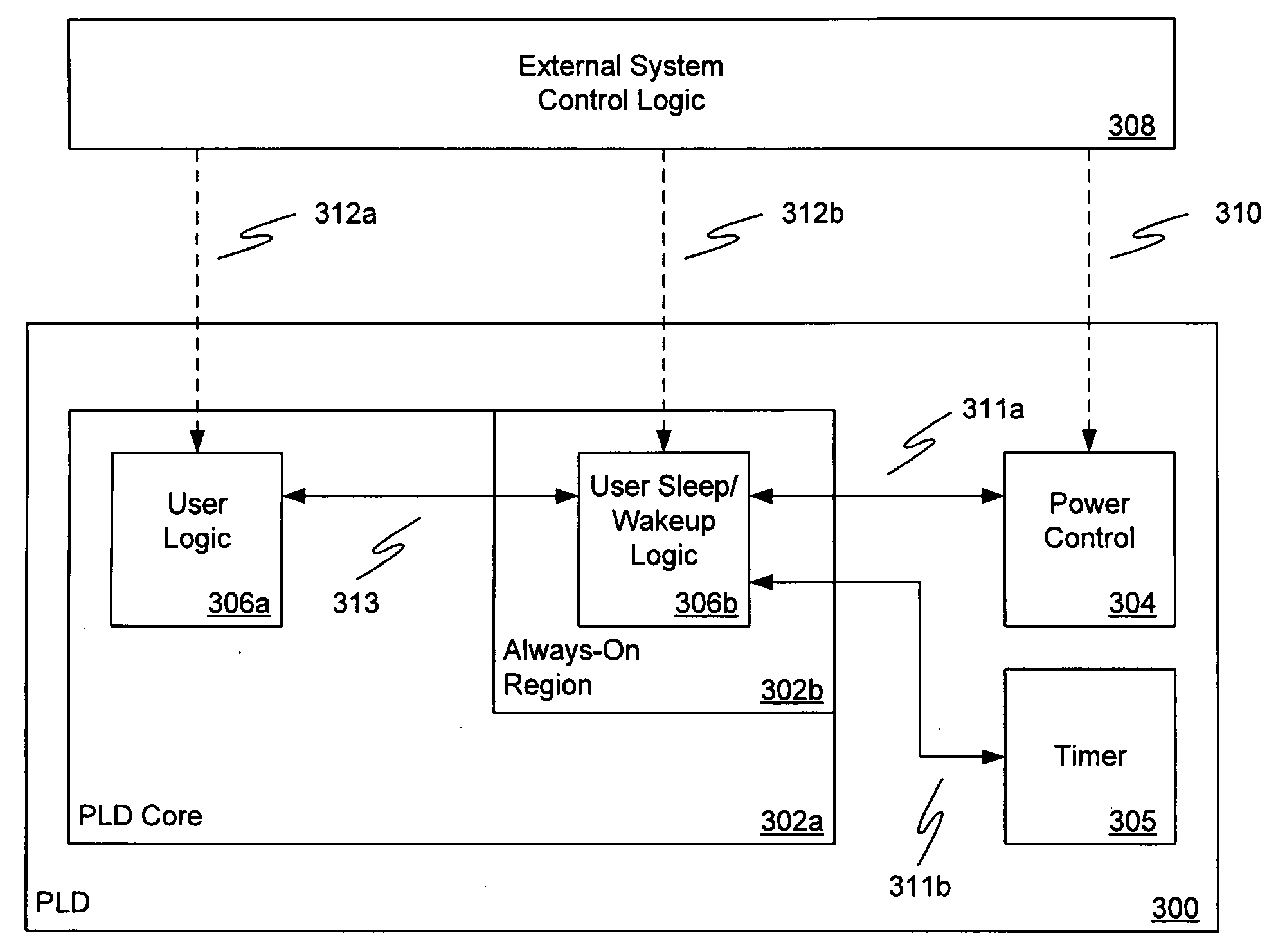
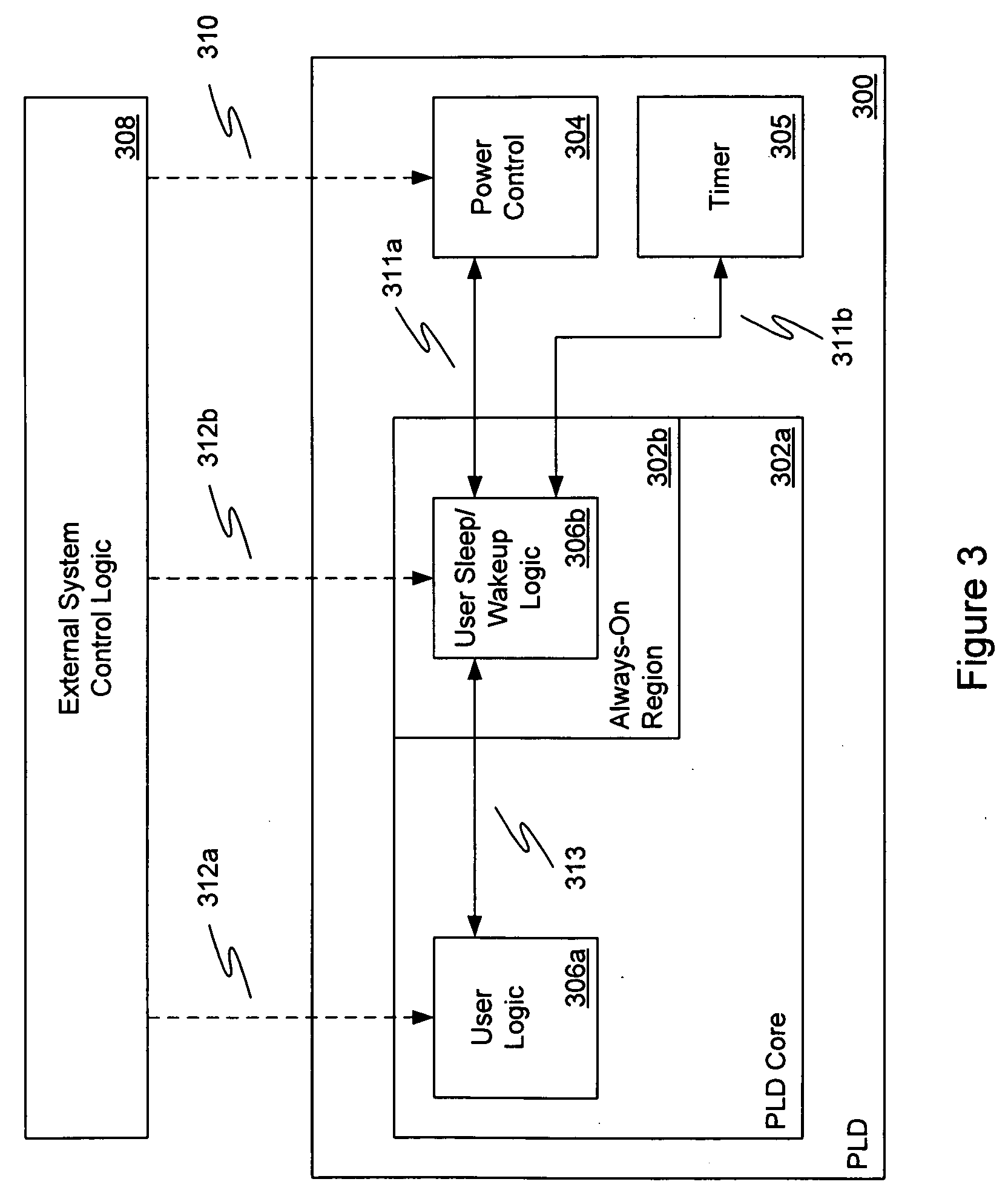
[0037]FIG. 3 shows an illustrative PLD 300 of the present invention. PLD 300 comprises a PLD core 302a that can be placed in a low-power or sleep mode. PLD core 302a has an always-on region 302b that always remains powered up as long as PLD 300 is powered up. The user's design is programmed into PLD core 302a and 302b together as a single design by the design software. The parts of the design that need to remain active during a low-power mode will be specified by the end user to be placed into always-on region 302b while the balance of the design will be placed into PLD core 302a which can be powered down (or otherwise placed in a low-power state with the power supplies still coupled to the power supply terminals in some embodiments)....


PUM


Abstract

A programmable logic device (PLD) with a plurality of programmable regions is disclosed. Some of the programmable regions have switch power or ground supplies to allow them to be put into a low-power state in one or more low-power modes. At least one of the programmable regions always remains on during the low-power modes to enable the user to design custom PLD power management logic that may be placed in the always-on programmable region.

Description

BACKGROUND OF THE INVENTION[0001]1. Field of the Invention[0002]The Present invention relates to the field of integrated circuits. In particular, it relates to power management in programmable logic integrated circuit devices.[0003]2. The Prior Art[0004]Programmable Logic Devices (PLDs) are known in the art. A PLD comprises any number of initially uncommitted logic modules arranged in an array along with an appropriate amount of initially uncommitted routing resources. Logic modules are circuits which can be configured to perform a variety of logic functions like, for example, AND-gates, OR-gates, NAND-gates, NOR-gates, XOR-gates, XNOR-gates, inverters, multiplexers, adders, latches, and flip / flops. Routing resources can include a mix of components such as, for example, wires, switches, multiplexers, and buffers. Logic modules, routing resources, and other features like, for example, I / O buffers and memory blocks, are the programmable elements of the PLD.[0005]The programmable eleme...

Claims


Application Information

Patent Timeline
Patent Type & Authority Applications(United States)
IPC IPC(8): H03K19/177H03K19/0175
CPCH03K19/17784
Inventor GREENE, JONATHAN W.BAKKER, GREGORYBELLIPPADY, VIDYADHARAHECHT, VOLKERSPEERS, THEODORE
Owner MICROSEMI SOC
Why Eureka
Try Eureka