Acoustic isolator

US20100157741A1Active Publication Date: 2010-06-24BAKER HUGHES OILFIELD OPERATIONS LLC

Image

  • Acoustic isolator
  • Acoustic isolator
  • Acoustic isolator

Examples


example 1

Kq=Ks=K

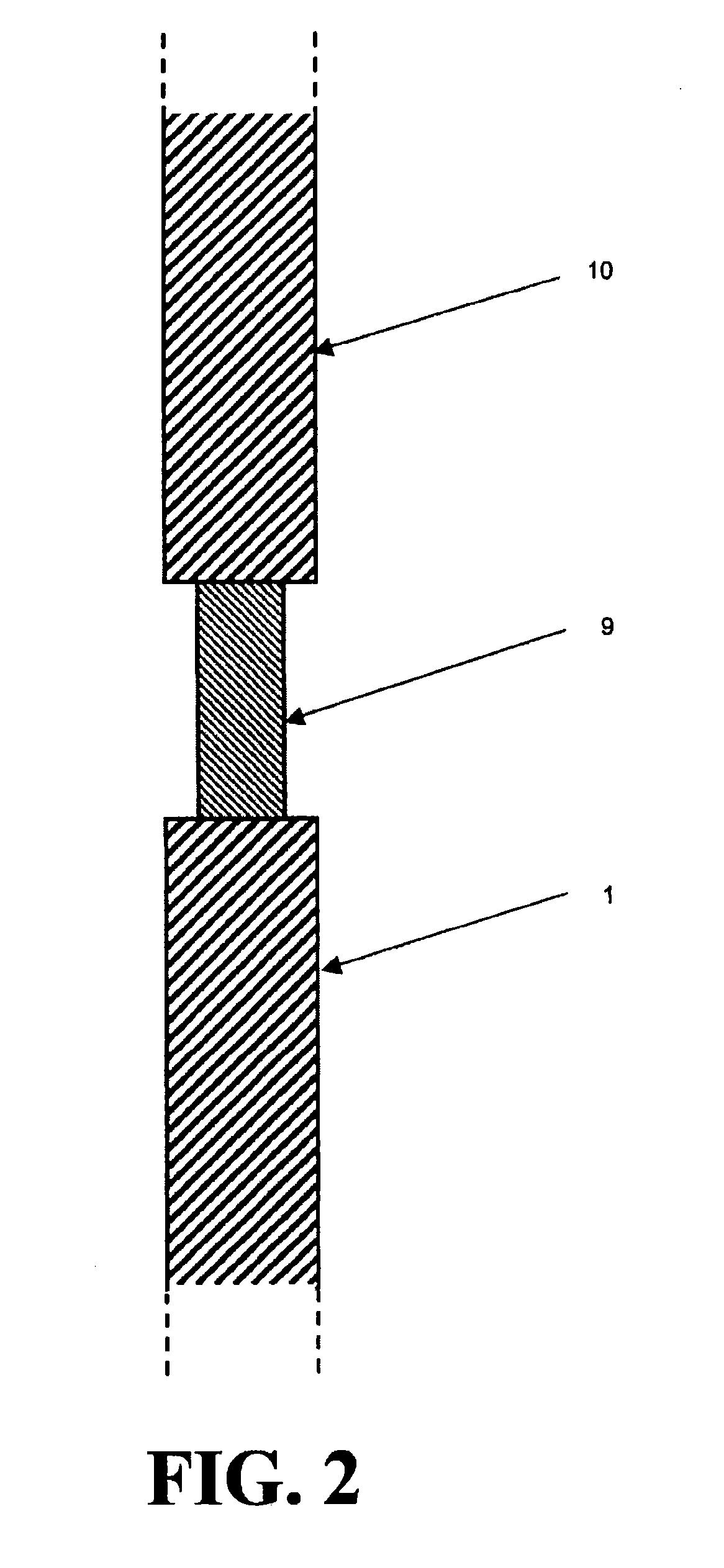
[0050]Referring now to FIG. 2, three segments are illustrated: (1) a first segment 1, which is a pipe with impedance z1; (2) a second segment 9, which is an noddλ / 4 length pipe with impedance z2; and (3) a third segment 10, which is a pipe with an impedance z3 that has the same impedance z1 as segment 1. In this case we see that equations [5] and [6] become:

R / I=(1−K2) / (1+K2)  [9]

and

T / I=2K / (1+K2)  [10]

where we now define K to be

Ks=Kq=(z1 / z2)≡K,  [11]

wherein z3=z1.

[0051]Equations [9] and [10] apply to an incident wave approaching the noddλ / 4 length section 9 from either direction. Where segments 1 and 10 are pipes that are standard oilfield alloy steel drill collars it is straightforward to calculate their acoustic impedance. In order to implement a significant impedance mismatch we could, for example, use a thin-walled, small diameter noddλ / 4 titanium pipe for segment 9, such that the impedance z2 of the segment 9 is less than that of segments 9 and 10. An attainable value for...

example 2

Kq≠Ks

[0060]In another example, the impedance of the snubber 13 is increased, to maximize the acoustic mismatch between it and the reflector tube 9. Because one may run into practical limitations associated with increasing the wall area (see equation [1]), an alternative is to vary the material mass density ρ. For example, as most components of the drillstring are steel the snubber 13 may be constructed from a hollow steel housing filled with lead. An attainable impedance mismatch between a titanium reflector 9 and a denser snubber 13 is Ks=14.3, and as before the impedance mismatch between the λ / 4 length tuning bar 15 / 16 and the λ / 4 length reflector bar 9 is Kq=7.8. Equations [5] and [6] then enable calculation of R / I=−0.982 and T / I=0.254. While these numbers do not immediately indicate a significant improvement in isolation we must also recognize that we have now created another impedance mismatch between the snubber [13] and the drill collar [12] that improves the isolation. This...


PUM


Abstract

An acoustic isolator for use with tubular assemblies such as drillpipe or production tubing comprising an acoustic wave transmitter, the acoustic isolator comprising, in series connection, an odd integer λ / 4 multiple tuning bar of first acoustic impedance adjacent the acoustic wave transmitter, an odd integer λ / 4 multiple reflector tube of second acoustic impedance, and a snubber of third acoustic impedance, wherein there is an acoustic impedance mismatch between the odd integer λ / 4 multiple tuning bar and the odd integer λ / 4 multiple reflector tube and an acoustic impedance mismatch between the odd integer λ / 4 multiple reflector tube and snubber, such that a ‘down’ wave propagated toward the isolator is reflected back substantially in phase with an ‘up’ wave propagated from the acoustic wave source away from the isolator. Furthermore, the acoustic isolator is similarly effective in reflecting ‘up’ propagating waves originating from below the isolator, hence further protecting the acoustic wave source from possible deleterious interference.

Description

CROSS REFERENCE TO RELATED APPLICATIONS[0001]The present application is a continuation-in-part of U.S. application Ser. No. 11 / 606,818, filed Dec. 1, 2006, which claims the benefit of U.S. Provisional application No. 60 / 741,907, filed Dec. 5, 2005. Application Ser. Nos. 11 / 606,818 and 60 / 741,907 are incorporated herein by reference.FIELD OF THE INVENTION[0002]The present invention relates to telemetry apparatus and methods, and more particularly to acoustic telemetry apparatus and methods used in the oil and gas industry.BACKGROUND OF THE INVENTION[0003]Acoustic telemetry is a method of communication in the well drilling and production industry. In a typical drilling environment, acoustic carrier waves from an acoustic telemetry device are modulated in order to carry information via the drillpipe to the surface. Upon arrival at the surface, the waves are detected, decoded and displayed in order that drillers, geologists and others helping steer or control the well are provided with ...

Claims


Application Information

Patent Timeline
24 Jun 2010
Publication
US20100157741A1
IPC
G01V1/00
CPC
G01V1/523
Inventors
DRUMHELLER, DOUGLAS S.; CAMWELL, PAUL L.