Recording/reproduction apparatus and recording/reproduction system

a recording/reproduction apparatus and recording/reproduction technology, applied in the field of recording/reproduction apparatus and recording/reproduction system, to achieve the effect of preventing cross-erasing of adjacent tracks, not easily heated, and suppressing spots

Inactive Publication Date: 2010-06-24
SONY CORP
View PDF9 Cites 5 Cited by
  • Summary
  • Abstract
  • Description
  • Claims
  • Application Information

AI Technical Summary

Benefits of technology

[0009]In the case where information is recorded directly on a recording medium through light, in general, recording marks to be formed are shrunk in the line direction compared to the spot shape of the light, and thus it is relatively easy to increase the recording density in the line direction. In the heat-assisted magnetic recording scheme, it is possible to increase the recording density in the line direction by utilizing technologies such as increasing the resolution of the magnetic field to be applied and a writing scheme with overlapping pits that uses pulsed light, in addition to reducing the spot size of near-field light.
[0014]In the present invention, as discussed above, the two conductor sections which produce near-field light are disposed such that a direction from one of the two conductor sections to the other of the two conductor sections is generally perpendicular to the line direction of the recording medium when information is recorded. With such a configuration, the two conductor sections, which are disposed in the direction perpendicular to the line direction of the recording medium, suppress the spread of spots formed by the near-field light in the direction perpendicular to the line direction of the recording medium. Therefore, adjacent tracks are not easily heated, preventing cross erasing of the adjacent tracks. Thus, according to the present invention, high-density recording is enabled in the direction perpendicular to the line direction of the recording medium (track pitch direction).

Problems solved by technology

Regarding the track pitch direction, in contrast, there is a problem of so-called “cross erasing” in which while information is being recorded in a recording track, an adjacent recording track is also heated to erase recording marks already recorded in the adjacent track, for both the optical recording scheme and the heat-assisted magnetic recording scheme discussed above.

Method used


Image

  • Recording/reproduction apparatus and recording/reproduction system
  • Recording/reproduction apparatus and recording/reproduction system
  • Recording/reproduction apparatus and recording/reproduction system

Examples


first embodiment

1. First Embodiment

Configuration for Near-field Light Generation

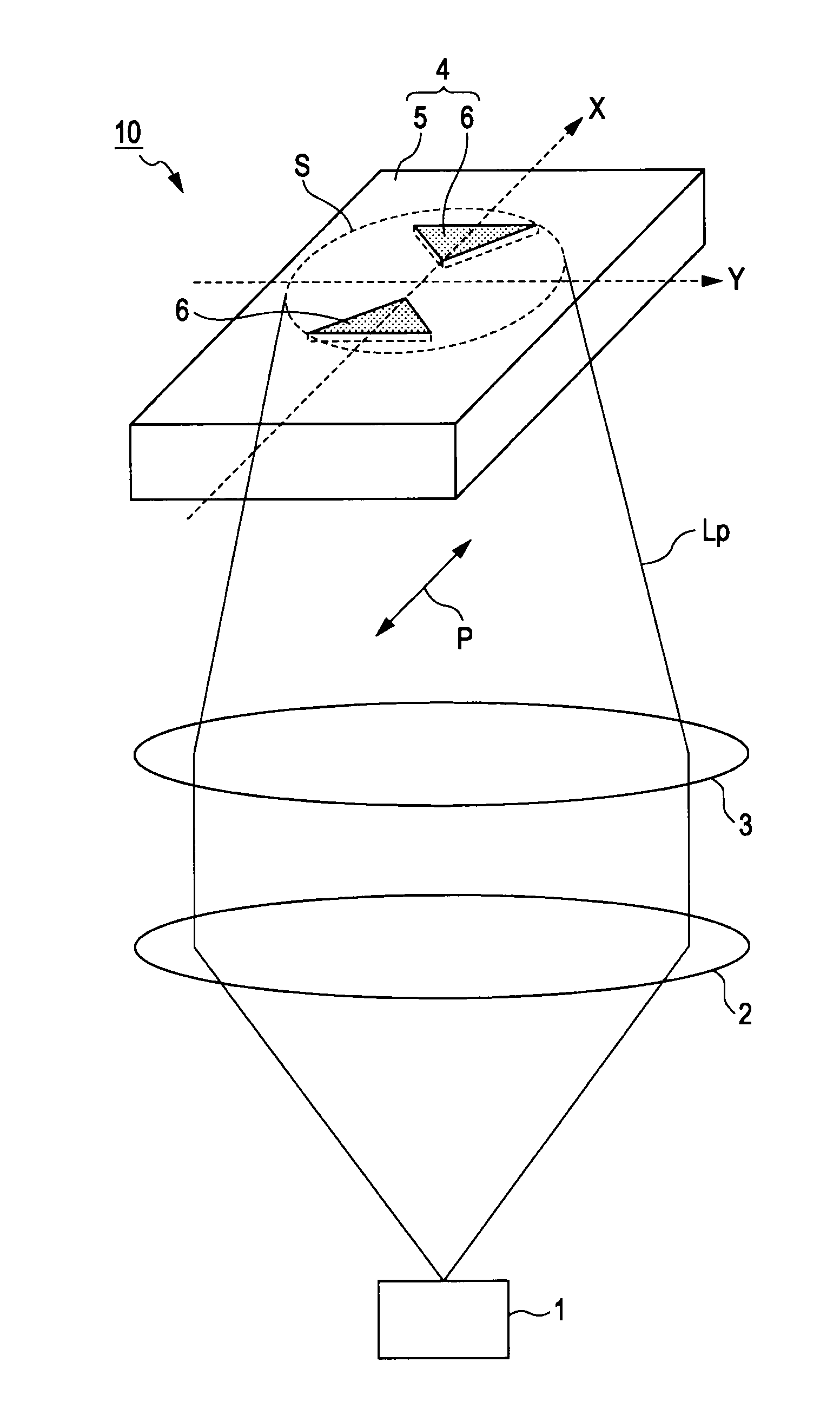
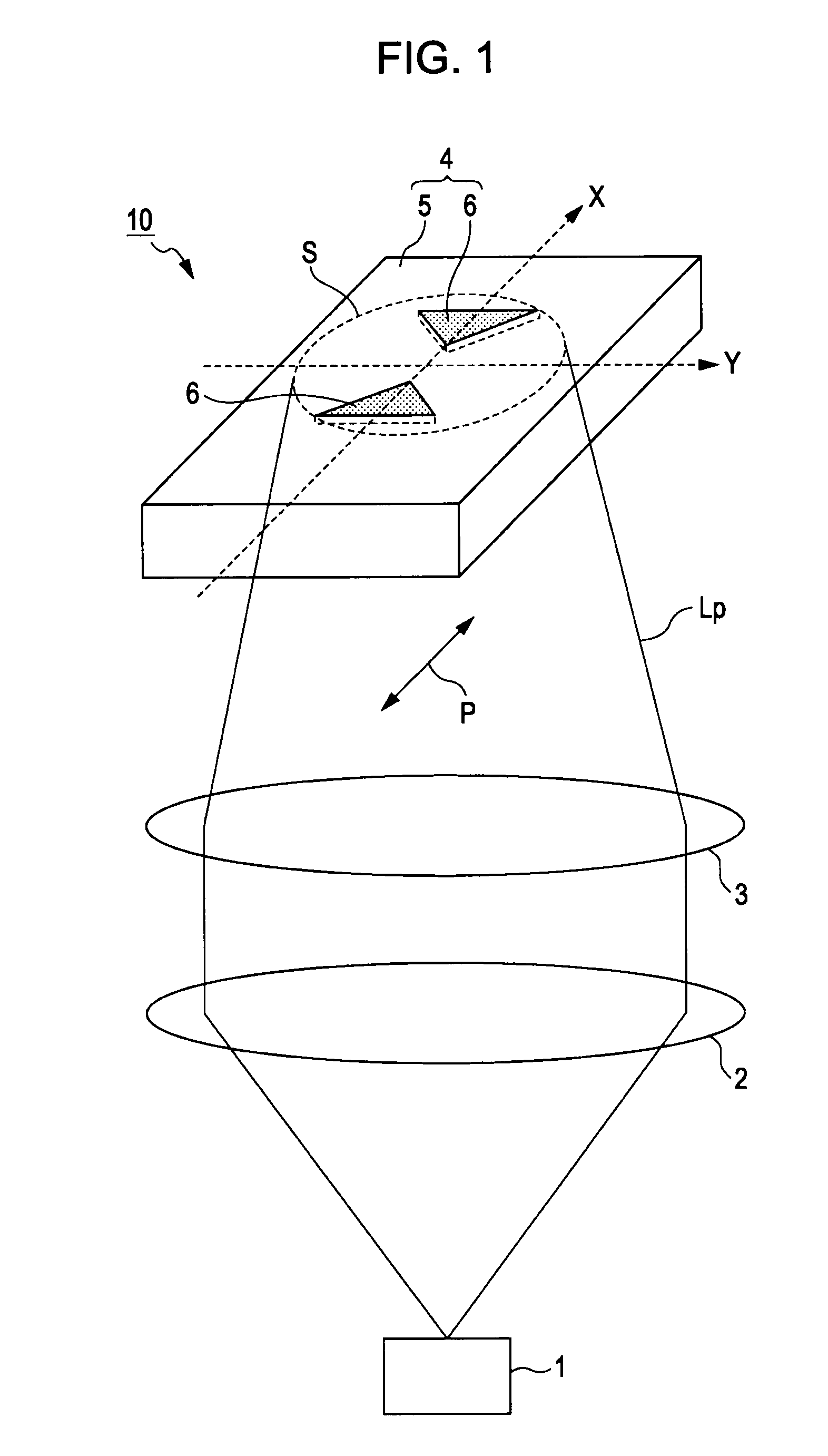
[0047]FIG. 1 shows an exemplary schematic configuration of a section that generates near-field light (hereinafter referred to as “near-field light generation section”) of a recording / reproduction apparatus according to a first embodiment of the present invention. The recording / reproduction apparatus according to the embodiment may be an optical recording apparatus or a heat-assisted magnetic recording apparatus that uses near-field light. A near-field light generation section 10 mainly includes a light source 1, a collimator lens 2, a condensing lens 3, and a near-field light production section 4.

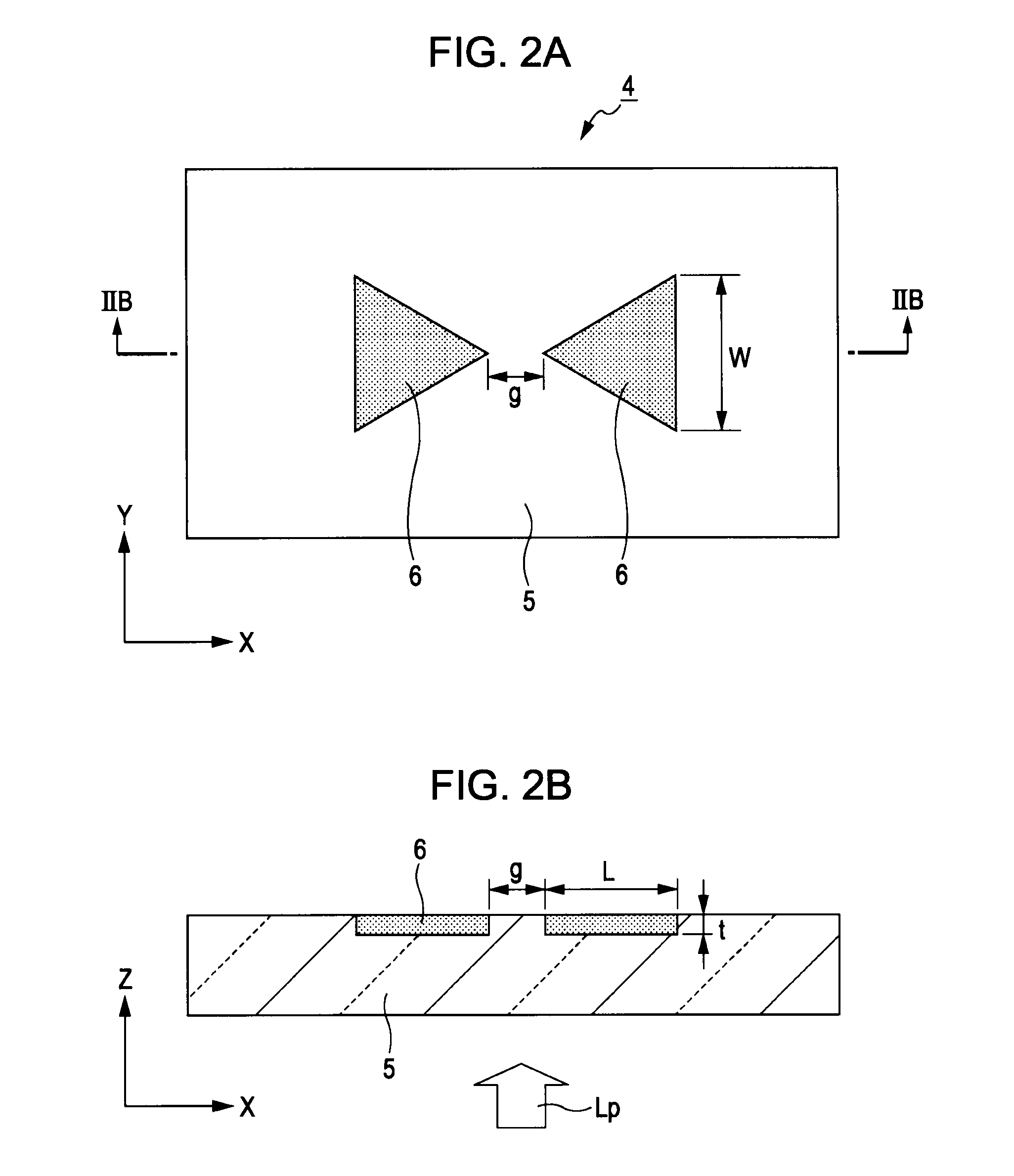
[0048]The light source 1 emits light polarized in a predetermined direction (hereinafter referred to as “propagation light”). In the embodiment, as shown in FIG. 1, the polarization direction P of the propagation light Lp is parallel to a direction from one of a pair of conductors 6 to the other of the pair of conductors 6 to b...

modification 1

2. Modification 1

[0071]Although the pair of conductors 6 of the near-field light production section 4 are disposed in a bow-tie arrangement in the first embodiment, the present invention is not limited thereto, and the arrangement of the pair of conductors 6 may be modified appropriately in accordance with use, specifications, and ease of fabrication, for example. Exemplary modified arrangements of the pair of conductors 6 are described below.

modification 1-1

[0072]FIG. 7 shows a top view of a pair of conductors disposed in accordance with a modification 1-1 (showing a surface opposing a recording medium). Two conductors 26 (conductor sections) according to the modification 1-1 are disposed in a so-called double rod arrangement. In the modification 1-1, respective surfaces of the two conductors 26 that oppose a recording medium have a rectangular shape that is the same for the two conductors 26. The conductors 26 are disposed such that one of the short sides of one conductor 26 opposes one of the short sides of the other. In the example of FIG. 7, the direction in which the respective short sides of the conductors 26 oppose each other (the direction along the long sides of the conductors 26) is defined as the X direction, the direction perpendicular to the X direction (the direction along the short sides of the conductors 26) is defined as the Y direction, and the direction of the thickness of the conductors 26 is defined as the Z direct...


PUM

PropertyMeasurementUnit
wavelengthaaaaaaaaaa
transparencyaaaaaaaaaa
sizeaaaaaaaaaa

Abstract

A recording / reproduction apparatus includes: a light source; and a near-field light production section that includes two conductor sections disposed opposite each other with a predetermined gap therebetween and that produces near-field light between the two conductor sections upon light irradiation from the light source, the two conductor sections being disposed such that when information is recorded on a recording medium using the near-field light, a direction from one of the two conductor sections to the other of the two conductor sections is generally perpendicular to a line direction of the recording medium.

Description

BACKGROUND OF THE INVENTION[0001]1. Field of the Invention[0002]The present invention relates to a recording / reproduction apparatus and a recording / reproduction system, and more particularly to a recording / reproduction apparatus and a recording / reproduction system that use near-field light.[0003]2. Description of the Related Art[0004]In recent years, technologies in which near-field light is utilized as recording light to record information on information recording media at a high density have been proposed. In the case where near-field light is used, it is possible to form minute light spots that exceed the diffraction limit of light. For example, a heat-assisted magnetic recording technology that uses near-field light is receiving attention as a promising next-generation high-density magnetic recording technology. There are proposals for various applications of near-field light to information recording media that use magneto-optical recording films or phase-change recording films....

Claims


Application Information

Patent Timeline
Patent Type & Authority Applications(United States)
IPC IPC(8): G11B11/00
CPCB82Y10/00G11B5/743G11B7/1387G11B2005/0021G11B11/10545G11B11/1058G11B2005/001G11B11/10536
Inventor HONGO, KAZUHIROWATANABE, TETSU
Owner SONY CORP
Why Eureka
Try Eureka