Hydraulic control device for automatic transmission

a technology of hydraulic control device and automatic transmission, which is applied in the direction of fluid couplings, gearings, couplings, etc., can solve the problems of increasing the size of the hydraulic control device, poor energy efficiency, and higher costs, and achieve the effect of reducing the temporary drop in the line pressur

Active Publication Date: 2010-07-01
AISIN AW CO LTD
View PDF4 Cites 7 Cited by
  • Summary
  • Abstract
  • Description
  • Claims
  • Application Information

AI Technical Summary

Benefits of technology

[0015]According to a fifth aspect of the present invention, the operation pressure supplied to the hydraulic servo of the friction engagement element whose engagement pressure is higher than for other friction engagement elements because it is frequently used and co...

Problems solved by technology

However, regulating the line pressure to a constant pressure increases the volume of oil consumption for constantly maintaining the line pressure to a high pressure, and results in poor energy efficiency.
A linear solenoid valve for line pressure control can be introduced in order to increase fuel efficiency while avoiding unnecessary increases to the line pressure, but t...

Method used


Image

  • Hydraulic control device for automatic transmission
  • Hydraulic control device for automatic transmission
  • Hydraulic control device for automatic transmission

Examples


Embodiment Construction

[0020]Embodiments of the present invention will be described below with reference to FIGS. 1 to 3.

General Configuration of Automatic Transmission

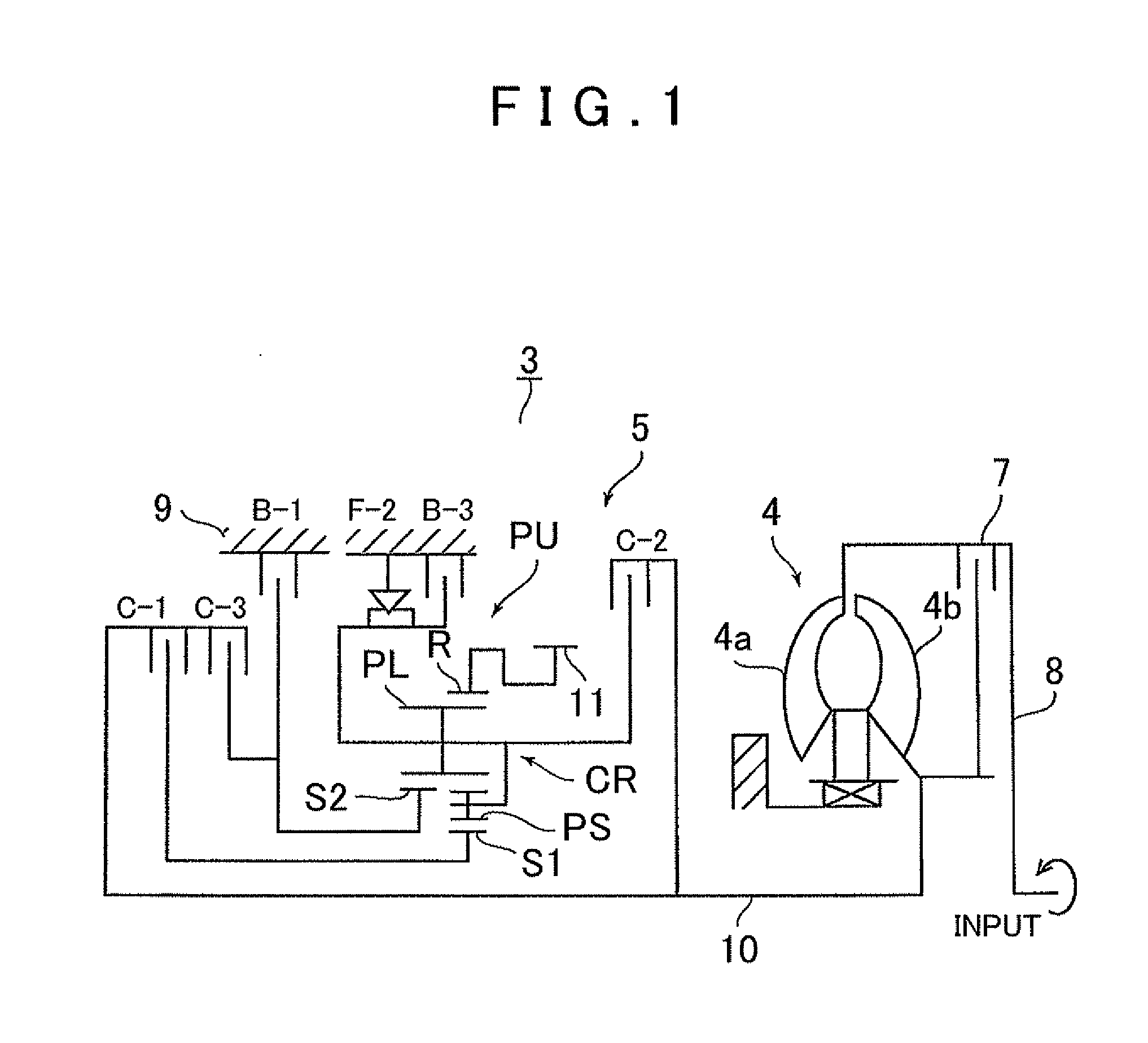
[0021]First, the overall configuration of an automatic transmission that can apply the present invention will be explained with reference to FIG. 1. As illustrated in FIG. 1, an automatic transmission 3 is well suited for use in a front-engine, front-wheel-drive (FF) vehicle, and has an input shaft 8 whereby the automatic transmission 3 can be connected to an engine. A torque converter 4 and an automatic speed change mechanism 5 are also provided centered around the axial direction of the input shaft 8.

[0022]The torque converter 4 has a pump impeller 4a that is connected to the input shaft 8 of the automatic transmission 3, and a turbine runner 4b to which the rotation of the pump impeller 4a is transmitted via a working fluid. The turbine runner 4b is connected to an input shaft 10 of the automatic speed change mechanism 5, which is coaxia...


PUM


Abstract

A hydraulic control device for an automatic transmission, including: a hydraulic pressure source; a plurality of friction engagement elements; a line pressure regulating valve that regulates hydraulic pressure from the hydraulic pressure source to a predetermined line pressure; a plurality of operation pressure regulating valves that regulate the line pressure as operation pressure for a hydraulic servo operating a friction engagement element; a maximum pressure conducting circuit that feeds a maximum pressure, among the operation pressures, to the line pressure regulating valve, wherein the friction engagement elements are engaged and released to achieve a plurality of forward speeds and a reverse speed, and the line pressure regulating valve regulates the line pressure during forward travel based on the maximum operation pressure, and regulates the line pressure during reverse travel based on the operation pressure input from a specific operation pressure regulating valve.

Description

INCORPORATION BY REFERENCE[0001]The disclosure of Japanese Patent Application No. 2008-330881 filed on Dec. 25, 2008 including the specification, drawings and abstract is incorporated herein by reference in its entirety.BACKGROUND OF THE INVENTION[0002]The present invention relates to a hydraulic control device for an automatic transmission installed in a vehicle such as an automobile or service vehicle. More specifically, the present invention relates to a hydraulic control device for an automatic transmission having a plurality of forward speeds and at least one reverse speed.DESCRIPTION OF THE RELATED ART[0003]An automatic transmission installed in a vehicle is generally structured so as to regulate a hydraulic pressure generated by an oil pump to a line pressure, that is, a source pressure of each hydraulic control device, using a regulating value such as a primary regulator valve. The regulating valve is formed so as to always regulate the line pressure to a constant pressure, ...

Claims


Application Information

Patent Timeline
IPC IPC(8): F16D25/10
CPCF16H3/663F16H61/0021
Inventor ISHIKAWA, TOMOMIKUTSUBO, HIROYUKISHIMIZU, TETSUYATSUCHIDA, KENICHIISHIKAWA, KAZUNORIFUKAYA, NAOYUKI
Owner AISIN AW CO LTD
Why Eureka
Try Eureka