Substrate Processing Apparatus and Substrate Mount Table Used in the Apparatus

a technology of substrate and processing apparatus, which is applied in the direction of coating, chemical vapor deposition coating, electric discharge tubes, etc., can solve the problems of inability to achieve in-plane temperature uniformity of wafer temperature distribution, cracking or breaking of susceptors, and low peripheral portion of the wafer support surface of susceptors, etc. to achieve the effect of in-plane temperature uniformity of wafers

Inactive Publication Date: 2010-07-01
TOKYO ELECTRON LTD
View PDF3 Cites 343 Cited by
  • Summary
  • Abstract
  • Description
  • Claims
  • Application Information

AI Technical Summary

Benefits of technology

[0009]Accordingly, the object of the present invention is to provide a substrate mount table that can achieve in-plane temperature uniformity of a wafer even if a precoating is applied to the substrate mount table for supporting a wafer, and also to provide a substrate processing apparatus provided with the substrate mount table.

Problems solved by technology

However, in a conventional susceptor, since the heat-dissipating amount at the peripheral portion is larger, the peripheral portion of the wafer support surface of the susceptor is likely to be relatively low.
As a result, the temperature of the wafer is higher in its center portion, and in-plane uniformity of the wafer temperature distribution can not be achieved.
However, in a case where the susceptor is made of a ceramic, if the temperature difference between the center portion and the peripheral portion is too large, it is possible that the susceptor is cracked or broken due to thermal stress.
Accordingly, only by the aforementioned technique, it is difficult to achieve in-plane uniformity of the wafer temperature distribution. FIG. 21 shows the result of the temperature measurement in a wafer plane while the wafer was heated by using a conventional susceptor.
Thus, the temperature of the center portion of the susceptor, which is a portion near the susceptor, greatly lowers as compared with other portions, causing non-uniformity of the wafer in-plane temperature distribution.
Thus, a sufficient level of in-plane temperature uniformity can not be achieved.

Method used


Image

  • Substrate Processing Apparatus and Substrate Mount Table Used in the Apparatus
  • Substrate Processing Apparatus and Substrate Mount Table Used in the Apparatus
  • Substrate Processing Apparatus and Substrate Mount Table Used in the Apparatus

Examples


Embodiment Construction

[0039]Preferred embodiments of the present invention will be described below with reference to the drawings.

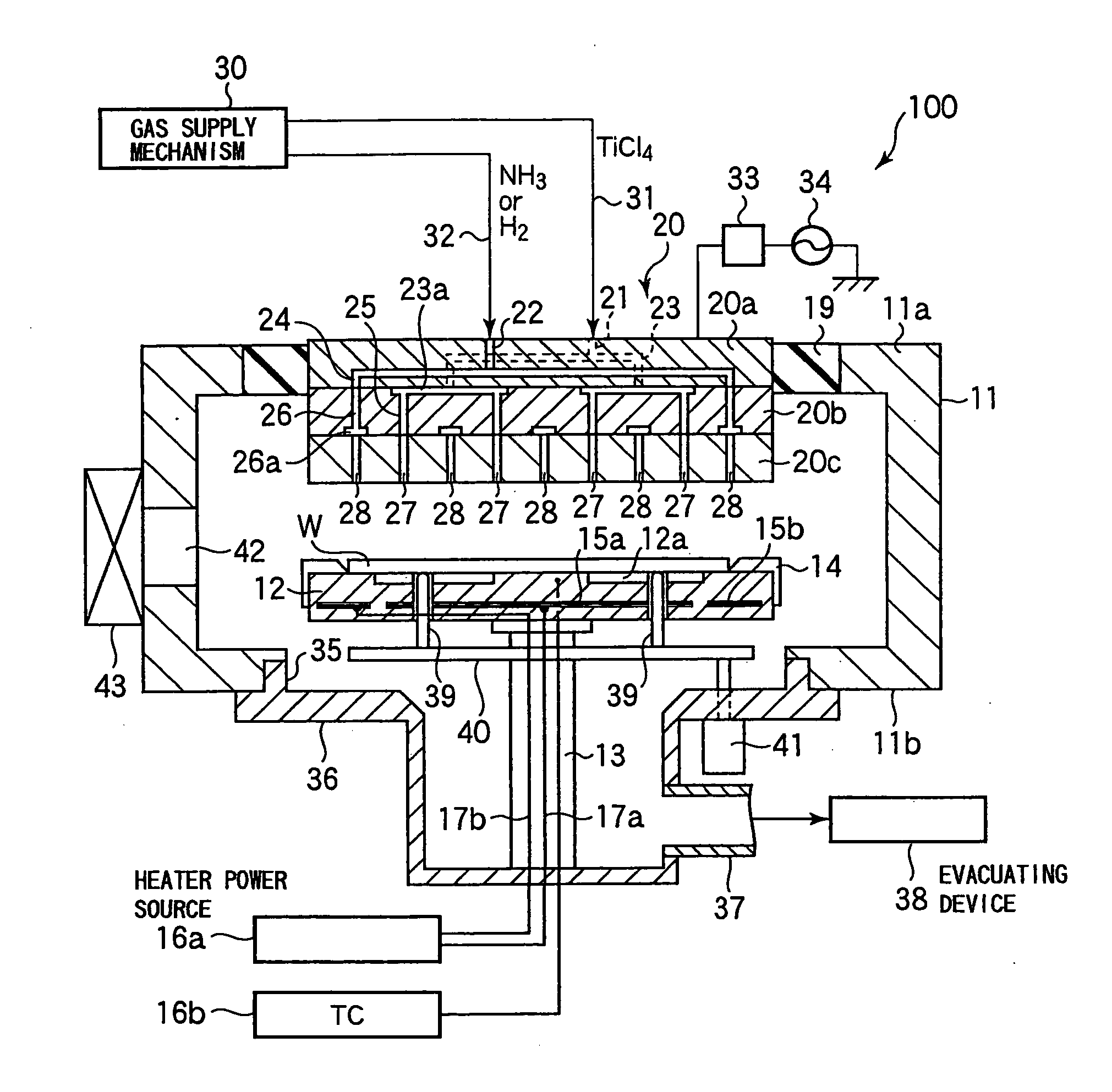
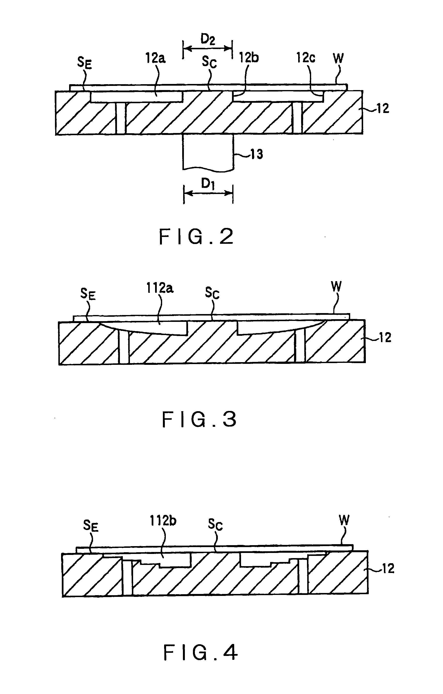
[0040]FIG. 1 is a cross sectional view of a film forming apparatus in a first embodiment of the present invention. The film forming apparatus 100 is for forming a TiN film or a Ti film, and includes a substantially cylindrical chamber 11. In the chamber 11, a discoid susceptor 12 for horizontally supporting a wafer W, which is a substrate to be processed, is supported by a cylindrical support member 13 that is disposed on a center bottom of the susceptor 12. The susceptor 12 is made of a ceramic such as Al2O3 and AlN. Herein, AlN is used. As described in detail below, a recess 12a is formed in a wafer support surface of the susceptor 12 at a position outside the center portion of the wafer support surface. A guide ring 14 for guiding a wafer W is disposed on an outer peripheral portion of the susceptor 12.

[0041]A heater 15a and a heater 15b as a heating means are embedded in t...


PUM

PropertyMeasurementUnit
temperatureaaaaaaaaaa

Abstract

Disclosed is a susceptor which achieves uniform temperature distribution of a wafer placed on the susceptor, and also disclosed is a substrate processing apparatus provided with the susceptor. An annular recess 12a is formed in an intermediate portion between the central portion and the peripheral portion of a wafer support surface of the susceptor 12. Due to the provision of the recess, the substrate heating effect by thermal radiation from the susceptor is suppressed in the intermediate portion. The geometrical dimension of the recess is determined taking the chamber internal pressure into consideration.

Description

TECHNICAL FIELD[0001]The present invention relates to a substrate processing apparatus that performs a heat treatment to a substrate such as a wafer or a predetermined treatment such as CVD while heating a substrate, and also relates to a substrate mount table used in the substrate processing apparatus.BACKGROUND ART[0002]In semiconductor device manufacturing processes, various kinds of gas processes, such as film forming processes and etching processes, are performed to a semiconductor wafer (hereinafter referred to simply as “wafer”) which is a substrate to be processed. In a CVD film deposition process of Ti, TiN or W among those processes, a wafer is heated up to, for example, about 500 to 700° C. by a resistance heater or a lamp heater while the wafer is placed on a susceptor formed of a ceramic or a metal.[0003]At this time, in view of uniformity of the process, in-plane uniformity of the wafer temperature distribution is necessary. To this end, uniformization of the susceptor...

Claims


Application Information

Patent Timeline
Patent Type & Authority Applications(United States)
IPC IPC(8): H01L21/683C23C16/00C23C16/46H01L21/477
CPCC23C16/4586H01J2237/2001H01L21/67109H01L21/68735H01L21/68742H01L21/683H01L21/3065C23C16/46H01L21/205
Inventor MURAKAMI, SEISHIOGOSE, KEI
Owner TOKYO ELECTRON LTD
Why Eureka
Try Eureka