
Electric power tools

a technology of electric power tools and power tools, which is applied in the direction of portable power-driven tools, manufacturing tools, drilling machines, etc., can solve the problems of adverse effects, capacitors to become large in size, and surge voltage that will occur larg

Inactive Publication Date: 2010-07-01
MAKITA CORP
View PDF10 Cites 32 Cited by
  • Summary
  • Abstract
  • Description
  • Claims
  • Application Information

AI Technical Summary

Benefits of technology

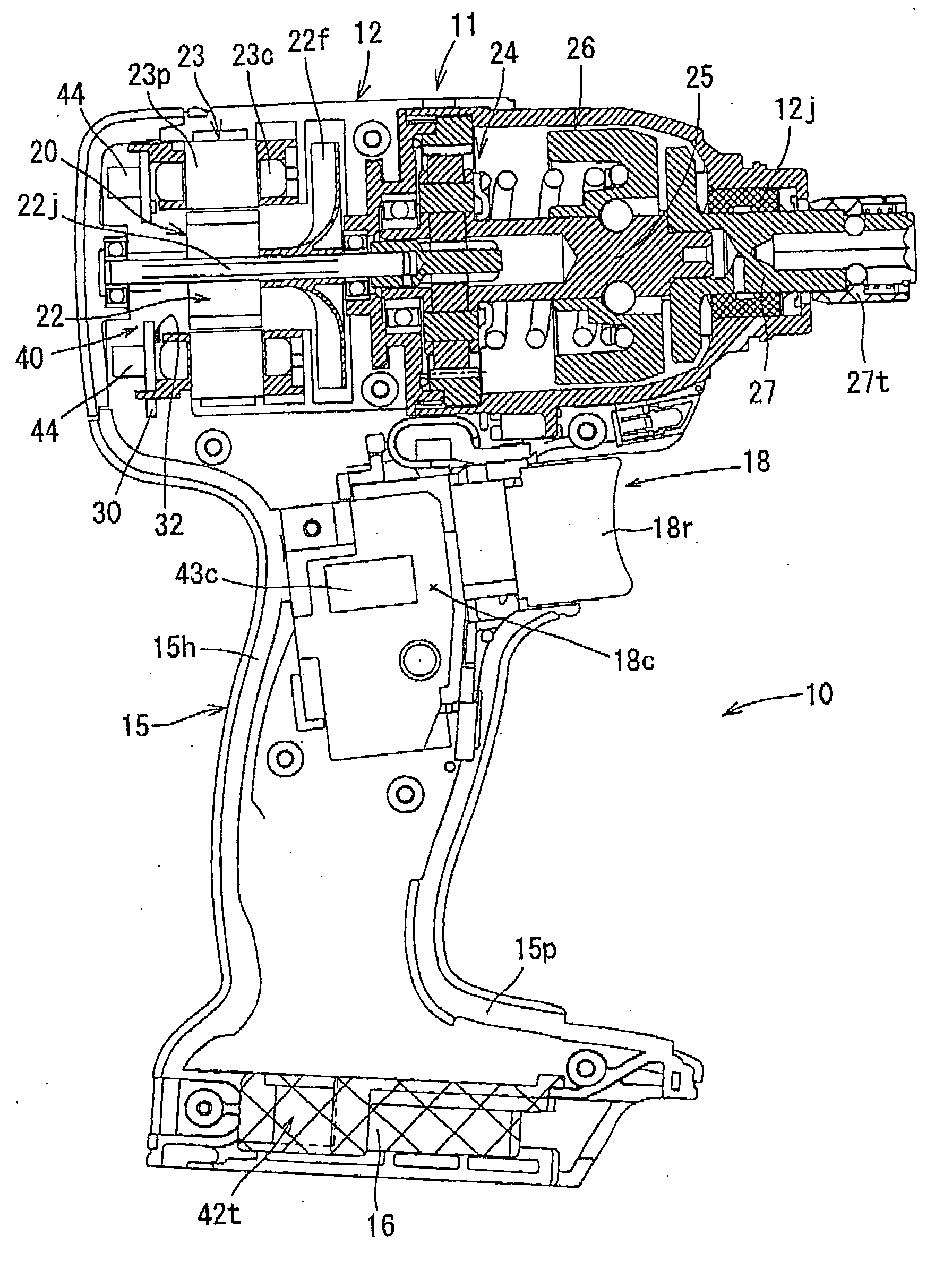
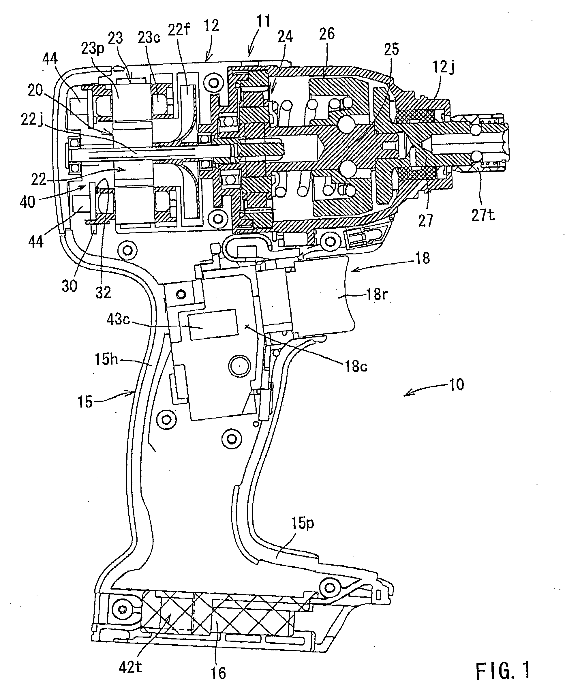
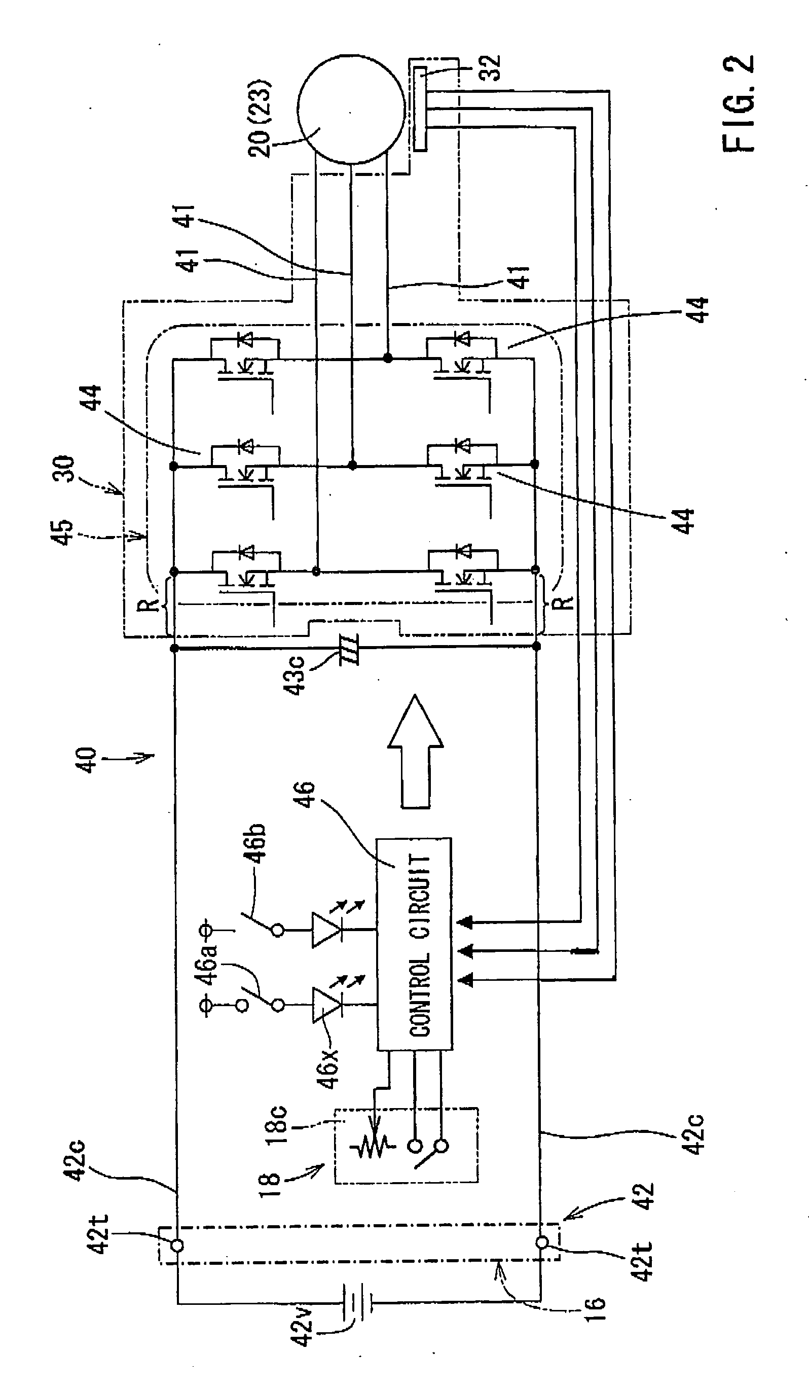
[0019]In one embodiment, an electric power tool includes a housing body part for housing a brushless DC motor as a driving source, a grip part formed to protrude from a lateral part of the housing body part, a switch part provided in a position allowing a user to engage the switch part by his or her finger while the user holds the grip part, a battery that supplies a power to the brushless DC motor, a three-phase bridge circuit for controlling the blushless DC motor, a switching device constituting a part of the three-phase bridge circuit, and a capacitor connected in parallel with the three-phase bridge circuit. The three-phase bridge circuit is disposed proximate to the brushless DC motor in the housing body part, and the capacitor is disposed at a position proximate to a switch part or located closer to the three-phase bridge circuit than to the switch part. The electric power tool further includes an electric conductor that electrically connects the capacitor and the three-phase bridge circuit, and the three-phase bridge circuit is configured to connect the capacitor and the three-phase bridge circuit at the shortest distance.
[0012]Therefore, there is a need in the art for a power tool that can lower a withstand voltage of a switching device as much as possible and enables a capacity of a capacitor to be decreased as small as possible by suppressing a surge voltage caused by the operation of the switching device.

Problems solved by technology

Especially, when an on-off control of large current is made by the switching device in order to control the rotational speed of a high-powered motor that may be installed in an electric power tool, a surge voltage that will occur becomes large.
That is, compactification of the switching device causes the capacitor to become large in size.
For this reason, if the lead wire is long and the current applied to the switching device during the pulse-width modulation control is large, this may adversely affect when determining a withstand voltage of the switching device and a capacity of the capacitor connected in parallel with the three-phase bridge circuit part
Further, in the case that a switching device is used with relatively small in size and with low withstand voltage, a current applied to the switching device must be controlled and performance cannot be fully elicited from a high-powered motor that may be installed in an electric power tool.
Further, this may adversely affect to increase a battery voltage.

Method used


Image

  • Electric power tools
  • Electric power tools
  • Electric power tools

Examples


Embodiment Construction

[0018]Each of the additional features and teachings disclosed above and below may be utilized separately or in conjunction with other features and teachings to provide improved electric power tools. Representative examples of the present invention, which examples utilize many of these additional features and teachings both separately and in conjunction with one another, will now be described in detail with reference to the attached drawings. This detailed description is merely intended to teach a person of skill in the art further details for practicing preferred aspects of the present teachings and is not intended to limit the scope of the invention. Only the claims define the scope of the claimed invention. Therefore, combinations of features and steps disclosed in the following detailed description may not be necessary to practice the invention in the broadest sense, and are instead taught merely to particularly describe representative examples of the invention. Moreover, various...


PUM

PropertyMeasurementUnit
poweraaaaaaaaaa
distanceaaaaaaaaaa
rotational speedaaaaaaaaaa

Abstract

One aspect according to the present invention includes an electric power tool, in which a capacitor is positioned closer to a motor control circuit than a switch electrically connected to the motor control circuit.

Description

[0001]This application claims priority to Japanese patent application serial number 2008-333526, the contents of which are incorporated herein by reference.BACKGROUND OF THE INVENTION[0002]1. Field of the Invention[0003]The present invention relates to electric power tools including a housing body part for housing a blushless DC motor as a driving source, a grip part formed to protrude from a lateral part of the housing body part, a switch part provided in a position allowing a user to engage the switch part by his or her finger while the user holds the grip part, a battery that supplies a power to the blushless DC motor, a three-phase bridge circuit for controlling the blushless DC motor, a switching device constituting a part of the three-phase bridge circuit part, and a capacitor connected in parallel with the three-phase bridge circuit.[0004]2. Description of the Related Art[0005]In many electric power tools such as a driver or a drill for tightening screws or drilling holes, a ...

Claims


Application Information

Patent Timeline
Patent Type & Authority Applications(United States)
IPC IPC(8): B25F5/00
CPCB25F5/02H02K11/33
Inventor MATSUNAGA, YUTAKAKUSAKAWA, TAKUYAOMURA, MOTOHIRO
Owner MAKITA CORP
Learn More