Microscope objective

a technology of objective and microscopy, which is applied in the field of microscope objective, can solve the problems of affecting the active state of the cell by the stimulus itself, the cover glass is attended with a fabrication error, and the cover glass cannot be completely compensated by the objective, etc., and achieves wide field, large numerical aperture, and high extensiveness.

Inactive Publication Date: 2010-07-01
EVIDENT CORP
View PDF4 Cites 6 Cited by
  • Summary
  • Abstract
  • Description
  • Claims
  • Application Information

AI Technical Summary

Benefits of technology

[0038]According to the present invention, it is possible to obtain a microscope objective that is applicable to a microscope or microscope system with high extensiveness and a large numerical aperture to realize acquisition of a feeb

Problems solved by technology

In the fluorescence observation, when some stimulus is given to the living specimen, for example, by irradiation with exciting light, there is a possibility that the stimulus itself adversely affects an active state of the cell.
However, the cover glass is attended with a fabrication error.
Thus, when the thickness of the cover glass is varied to differ from that of the reference value, aberrations produced in accordance with variation of th

Method used


Image

  • Microscope objective
  • Microscope objective
  • Microscope objective

Examples


embodiment 1

[0091]In accordance with the drawings, the embodiments of the present invention will be explained below.

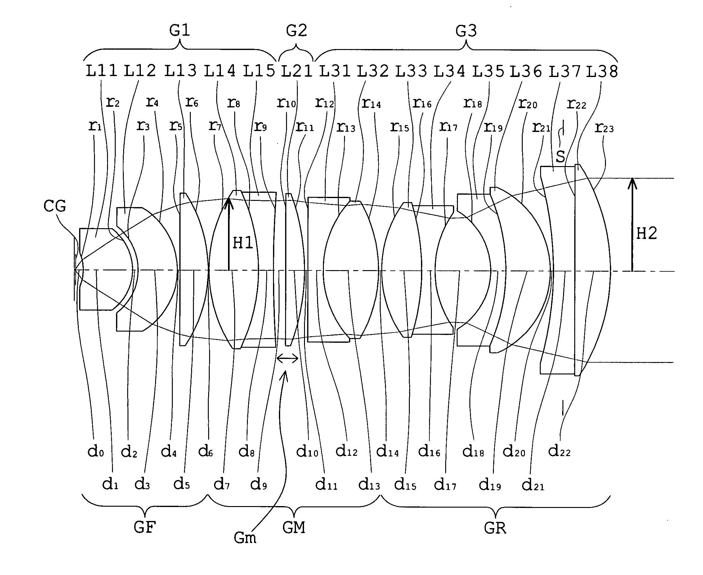
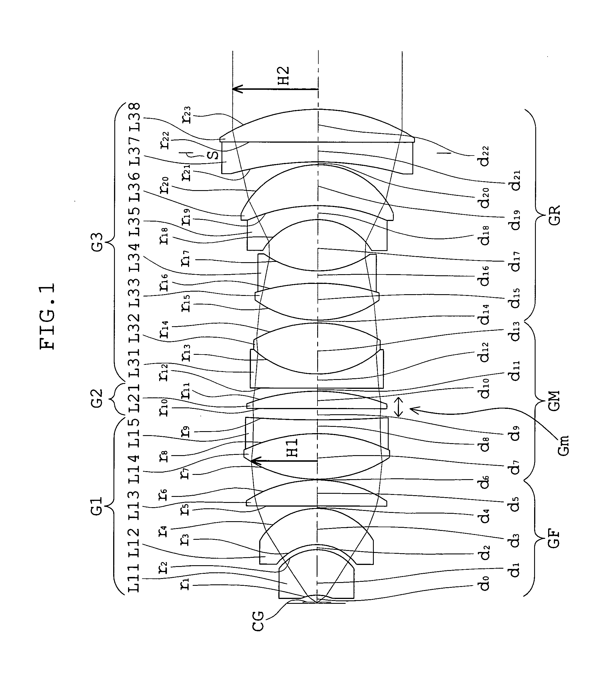
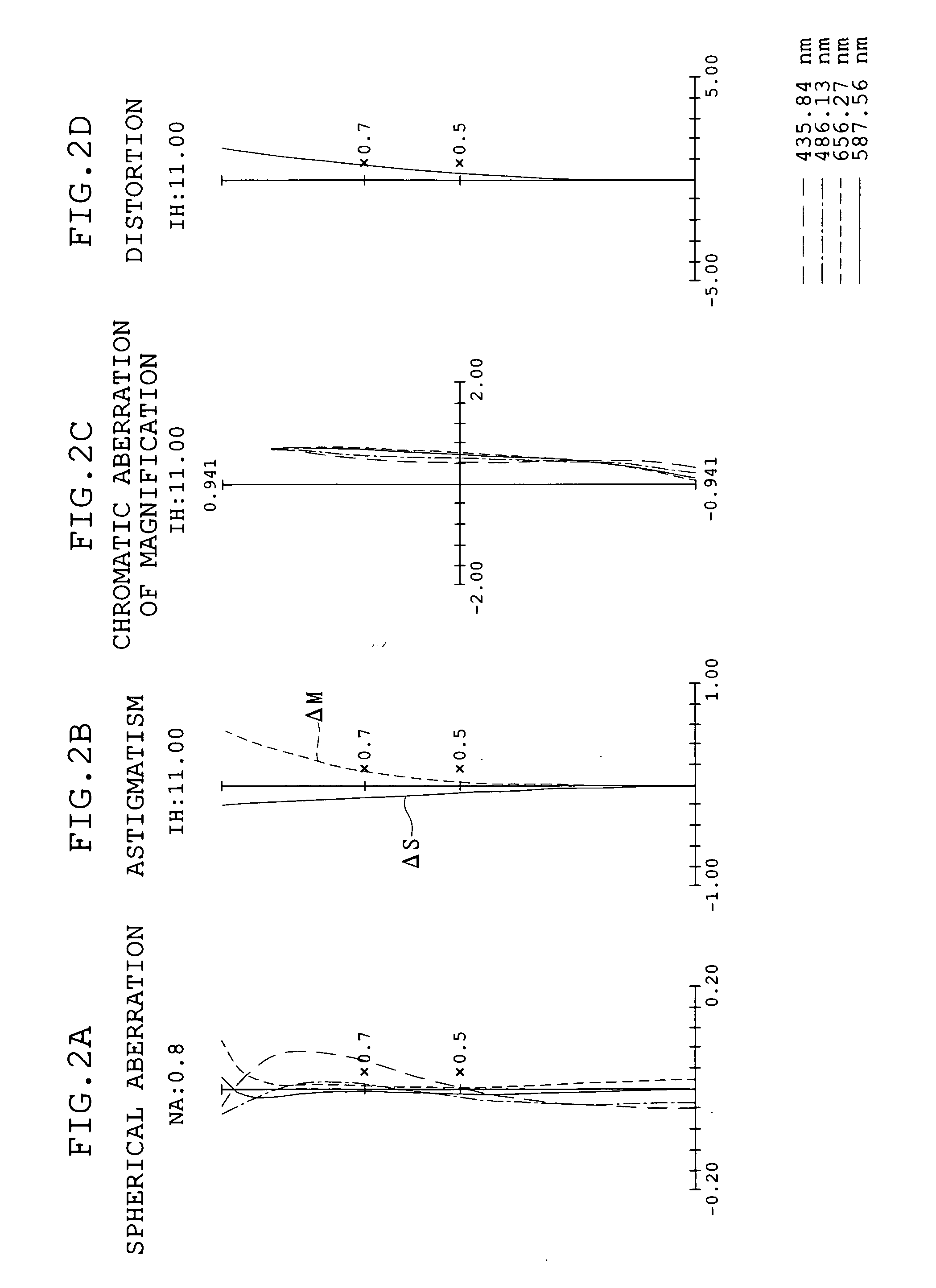
[0092]FIG. 1 shows a schematic arrangement, developed along the optical axis, of Embodiment 1 of the microscope objective according to the present invention. FIGS. 2A, 2B, 2C, and 2D are graphs showing spherical aberration, astigmatism, chromatic aberration of magnification, and distortion, respectively, of the microscope objective in Embodiment 1, in a case where the distance between the objective and an imaging lens (tube lens unit) is 80 mm.

[0093]The microscope objective of Embodiment 1 includes, in order from the object side, a first lens unit G1, a second lens unit G2, and a third lens unit G3. Also, in FIG. 1, reference symbol CG represents a cover glass.

[0094]The first lens unit G1 includes, in order from the object side, a positive meniscus lens L11 with a concave surface facing the object side, a negative meniscus lens L12 with a concave surface facing the object side, a ...

embodiment 2

[0103]FIG. 3 shows a schematic arrangement of Embodiment 2 of the microscope objective according to the present invention. FIGS. 4A, 4B, 4C, and 4D are graphs showing spherical aberration, astigmatism, chromatic aberration of magnification, and distortion, respectively, of the microscope objective in Embodiment 2, in a case where the distance between the objective and an imaging lens (tube lens unit) is 80 mm.

[0104]The microscope objective of Embodiment 2 includes, in order from the object side, a first lens unit G1, a second lens unit G2, and a third lens unit G3. Also, in FIG. 3, reference symbol CG represents a cover glass.

[0105]The first lens unit G1 includes, in order from the object side, a positive meniscus lens L11 with a concave surface facing the object side, a positive meniscus lens L12′ with a concave surface facing the object side, a biconvex lens L13′(Gm2), and a cemented doublet of a biconvex lens L14 and a biconcave lens L15, and has positive refracting power as a wh...


PUM


Abstract

A microscope objective includes at least five lens components, which are divided into three groups that are, in order from an object side: a front group having a positive refracting power as a whole and having a meniscus lens component with an object-side surface thereof being concave toward the object side; a middle group having a positive refracting power as a whole and having a plurality of cemented lens components; and a rear group having a pair of concave air-contact surfaces arranged adjacent and opposite to one another,
    • wherein the following conditions are satisfied:
3≦D0/f≦6
1≦H2/H1≦1.5
where D0 is an axial distance from an object surface to a rearmost surface of the microscope objective, f is a focal length of the microscope objective, H2 is a height of a marginal ray as emergent from the rearmost surface of the microscope objective, and H1 is a maximum height of the marginal ray as passing through the front group and the middle group.

Description

[0001]This application is a continuation-in-part of application Ser. No. 11 / 999,644 filed on Dec. 5, 2007, which claims benefits of Japanese Application No. 2007-021643 filed in Japan on Jan. 31, 2007.BACKGROUND OF THE INVENTION[0002]1. Field of the Invention[0003]This invention relates to a microscope objective applicable to a microscope or microscope system with high extensiveness that provides a large numerical aperture to realize acquisition of a feeble luminous signal at a high S / N ratio in microscopy while having a wide observation range.[0004]To be specific, this invention relates to a microscope objective that provides a wide observation range, a large entrance-side numerical aperture. NA to assure a high resolution, a large exit-side numerical aperture NA′ to realize acquisition of a feeble luminous signal at a high S / N ratio, and a good aberration performance.[0005]2. Description of Related Art[0006]In the most advanced research field at present, various methods of observi...

Claims


Application Information

Patent Timeline
IPC IPC(8): G02B21/02
CPCG02B7/008G02B2207/113G02B21/02G02B7/028
Inventor YONETANI, ATSUSHI
Owner EVIDENT CORP
Why Eureka
Try Eureka