
High-discharge-rate lithium ion battery

a lithium ion battery, high discharge rate technology, applied in the direction of cell components, final product manufacturing, sustainable manufacturing/processing, etc., can solve the problems of battery activation, dramatic changes in lithium ion cell performance, etc., to achieve significant improvement in cell cycleability and performance.

Inactive Publication Date: 2010-07-01
RGT UNIV OF CALIFORNIA
View PDF5 Cites 20 Cited by
  • Summary
  • Abstract
  • Description
  • Claims
  • Application Information

AI Technical Summary

Benefits of technology

The present invention provides a lithium ion battery with improved electronic conductivity using porous composite electrodes. The battery includes a mixture of carbon conductor, binder, NMP solvent, and active material, coated onto conductive foils to form electrodes. The electrodes are assembled into a cell housing with a porous separator between them. The technical effects of this invention include increased performance and improved cell cycleability. The invention also provides a method for fabricating the electrodes and a lithium battery using the fabricated electrodes.

Problems solved by technology

However, solid electrolytes and organic solvents are easily decomposed on anodes during charging, thus preventing battery activation.
These techniques have not resulted in dramatic changes in lithium ion cell performance increases.

Method used


Image

  • High-discharge-rate lithium ion battery
  • High-discharge-rate lithium ion battery
  • High-discharge-rate lithium ion battery

Examples


example 1

Fabrication of Gen2 Lithium Ion Pouch Cells Utilizing Mixing Sequence 1

[0107]The following is exemplary of general procedures useful for fabricating electrodes and pouch cell batteries based on Gen2 cathode material LiNi0.8CO0.15Al0.05O2 and Mag10 (graphite) anode material.

[0108]I. Cathode

[0109]The cathode electrode for Gen2 cell is composed of 84% LiNi0.8CO0.15Al0.05O2 active material, 4% acetylene black, 4% SFG-6 graphite (a second form of conductive additive) and 8% PVDF binder.

[0110]1. Slurry

[0111]It is found that pre-dispersion of acetylene black can be important for achieving a homogenous mixture, and low contact resistance for the laminate. Pre-dispersion is done by mixing 3 g of acetylene black with 50 mL of acetone and ten drops of Triton 100. This mixture is then ultrasonicated at 60% amplitude for 5 minutes in a Branson 450 sonifier. The mixture is then emerged in ice water to disperse the heat generated during sonication. The mixture is then concentrated using rotary eva...

example 2

Fabrication of LiMn2O4 (Spinel) / Graphite-Based Lithium Ion Pouch Cells Utilizing Mixing Sequence 1

[0142]The following exemplary procedures are useful for making electrodes and batteries of LiMn2O4 (spinel) and MCMB (meso carbon micro beads) graphite for high-power applications (HEVs) utilizing mixing sequence 1. Electrode performance can be very dependent on the materials used so it is pointed out that Toda M809 (LiMn2O4) was used for the cathode active material and MCMB 10-28 from Osaka Gas was used for the anode active material. The conductive additives were Dankon™ black, an acetylene black, and SFG-6, a micron-size graphite. The binder used is PVDF (Kureha 1100).

[0143]I. Cathode

[0144]1. Slurry for Both Electrodes

[0145]This slurry making procedure is optimized for both the spinel cathode material Toda M809 and the MCMB10-28 anode material.

[0146]The cathode electrode for a spinel cell is composed of 81.6% LiMn2O4 active material (Toda M809), 6.4% acetylene black (Dankon™), 4% SFG-...


PUM

PropertyMeasurementUnit
weight ratioaaaaaaaaaa

Abstract

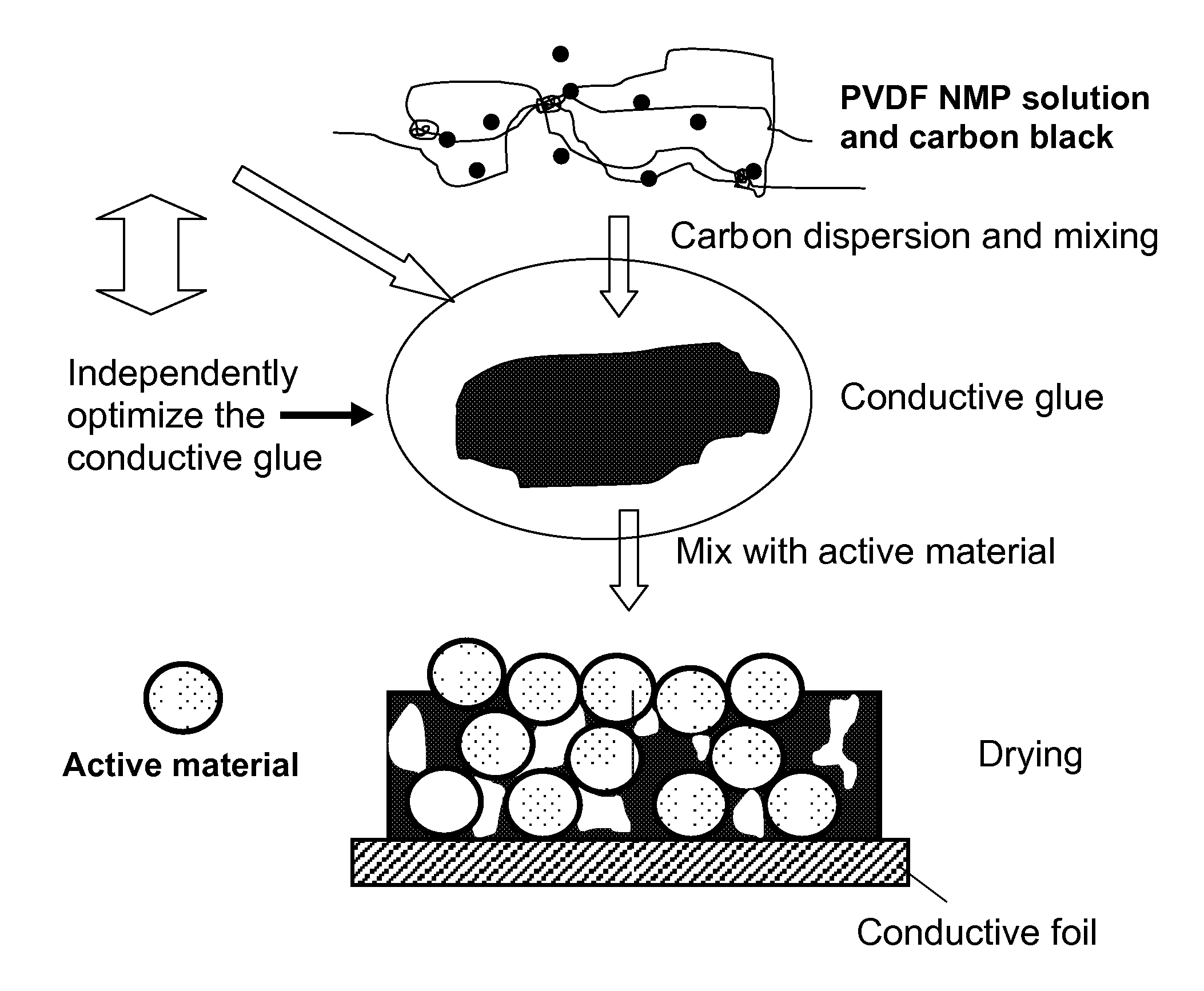
The present invention provides for a lithium ion battery and process for creating such, comprising higher binder to carbon conductor ratios than presently used in the industry. The battery is characterized by much lower interfacial resistances at the anode and cathode as a result of initially mixing a carbon conductor with a binder, then with the active material. Further improvements in cycleability can also be realized by first mixing the carbon conductor with the active material first and then adding the binder.

Description

CROSS REFERENCE TO RELATED APPLICATIONS[0001]This application is a continuation-in-part of, and claims the benefit of priority to International Application PCT / US2008063101, said application entitled High-Discharge-Rate Lithium Ion Battery, and having international filing date of May 8, 2008, which application in turn claims the benefit of priority to U.S. Provisional Application Ser. No. 60 / 916,715, filed May 8, 2007, entitled High-Discharge-Rate Lithium Ion Battery, both of which applications are incorporated by reference herein as if fully set forth in their entirety.STATEMENT OF GOVERNMENTAL SUPPORT[0002]The invention described and claimed herein was made in part utilizing funds supplied by the U.S. Department of Energy (DOE) under Contract No. DE-AC02-05CH11231 between the U.S. Department of Energy and the Regents of the University of California for the management and operation of the Lawrence Berkeley National Laboratory. The U.S. Government has certain rights in this inventio...

Claims


Application Information

Patent Timeline
Patent Type & Authority Applications(United States)
IPC IPC(8): H01M2/00H01M4/58H01M4/04H01M10/04B05D5/12H01M4/13H01M4/131H01M4/139H01M4/52H01M4/525H01M10/0525H01M10/36
CPCH01M4/0404H01M4/0435H01M4/13H01M4/131H01M4/139Y10T29/49108H01M4/622H01M4/625H01M10/0525Y02T10/7011H01M4/525Y02E60/10Y02P70/50Y02T10/70
Inventor LIU, GAOBATTAGLIA, VINCENT S.ZHENG, HONGHE
Owner RGT UNIV OF CALIFORNIA
Learn More