[0009]The method according to the invention is used to perform the complete
grinding process for the bar-shaped workpiece in two partial operations so that the entire
machining operation can be performed with a single grinding
machine in a
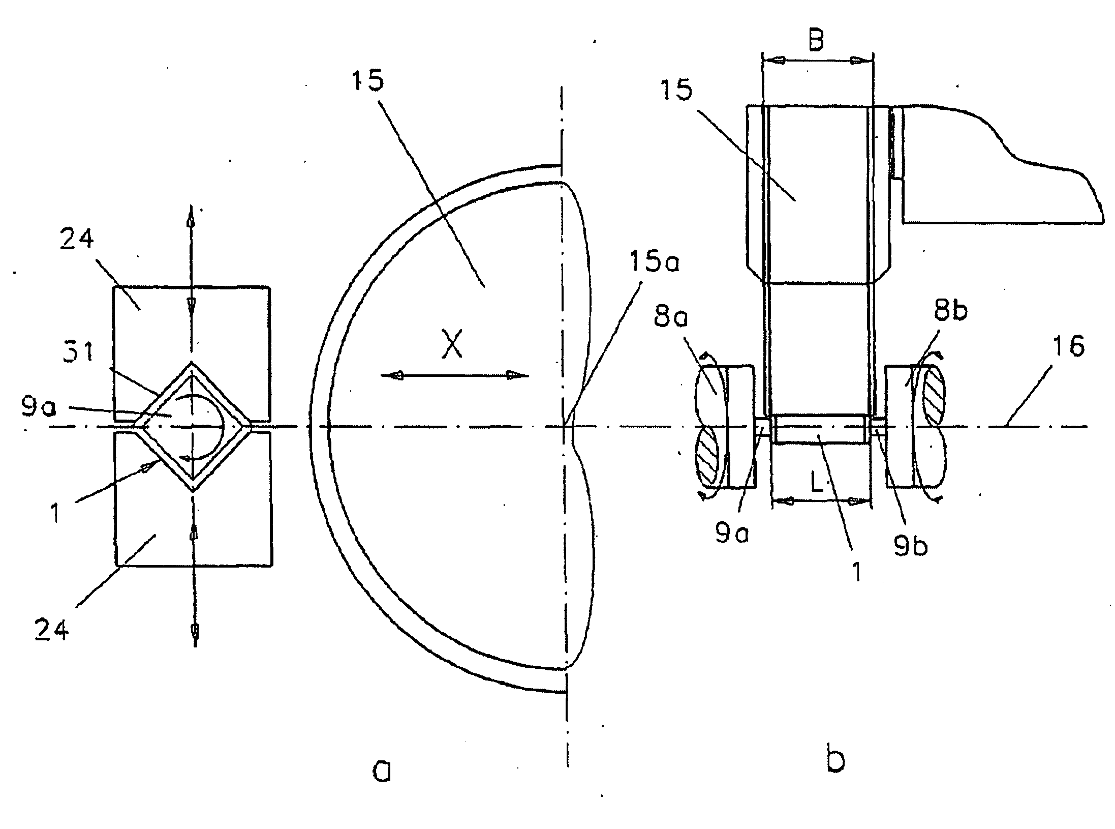
continuous production process. To this end, two different clamping positions, or clampings, which merge seamlessly, occur consecutively. First, each workpiece is clamped individually on the longitudinal sides thereof, such that it is not merely inserted into the chamfered recess of a carrier disk, which forms the first clamping position. In this position, the finishing of the two faces is performed. In general, the faces are rough ground and finished in this clamping position. However, there is no necessity for separate rough grinding at this point. When the clamping device is suitably configured, the double-disk face grinding operation produces excellent results on the faces. The workpiece, which is still in the clamped state, i.e., in the first clamping position, is then transferred between two clamping jaws, which are coaxially disposed at a distance from each other, by means of this clamping device and is clamped by these jaws at the faces thereof, which have already been finished, and therefore offer excellent conditions for precise subsequent
machining.
[0011]If the bar-shaped workpiece is machined based on non-circular grinding principles, as differs from
surface grinding, there is line contact between the
grinding wheel and the workpiece. As a result, the supply of
coolant is improved, and greater time saving is achieved, which considerably shortens
machining time.
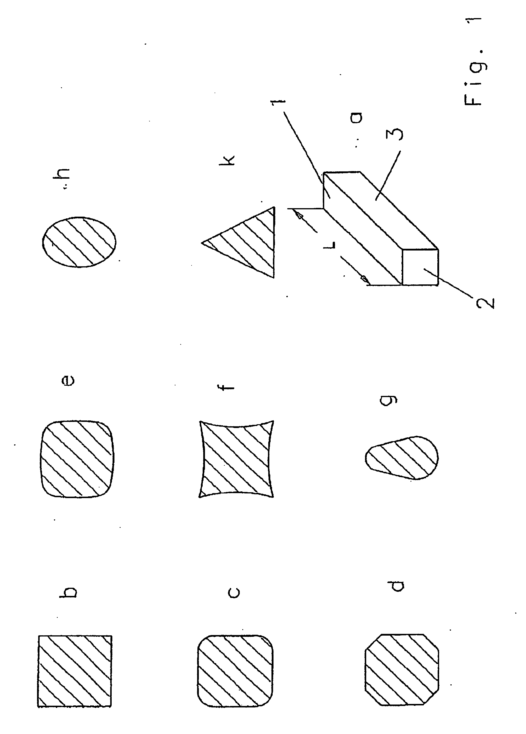
[0012]The CNC-controlled
peripheral grinding method can be used for rough grinding and finishing bar-shaped workpieces having various cross-sections, i.e., from simple square or rectangular cross-sections having rounded longitudinal edges, or flat chamfers on the longitudinal edges, to prismatic cross-sections, or cross-sections delimited by different curvatures, and combinations of these shapes. Being able to simply
grind flat longitudinal sides having chamfered or rounded edges in one operation, as well as cross-sections having consistently curved contours, avoids the problems of
burr formation resulting from face grinding. Selected possibilities are summarized by illustration in FIG. 1 of the embodiment.
[0022]The two grinding machines according to the foregoing approaches offer the
advantage that a single bar-shaped workpiece passes through the
machine at any given time, is face-ground on the faces in the first clamping position, and machined on the longitudinal sides by
peripheral grinding in the second clamping position. After passing through the grinding
machine, the grinding of the bar-shaped workpiece is finished. No parts need to be joined, thus reducing
space requirements. As a result, the prerequisites for optimal
continuous flow production are met. The required handling times are minimal.
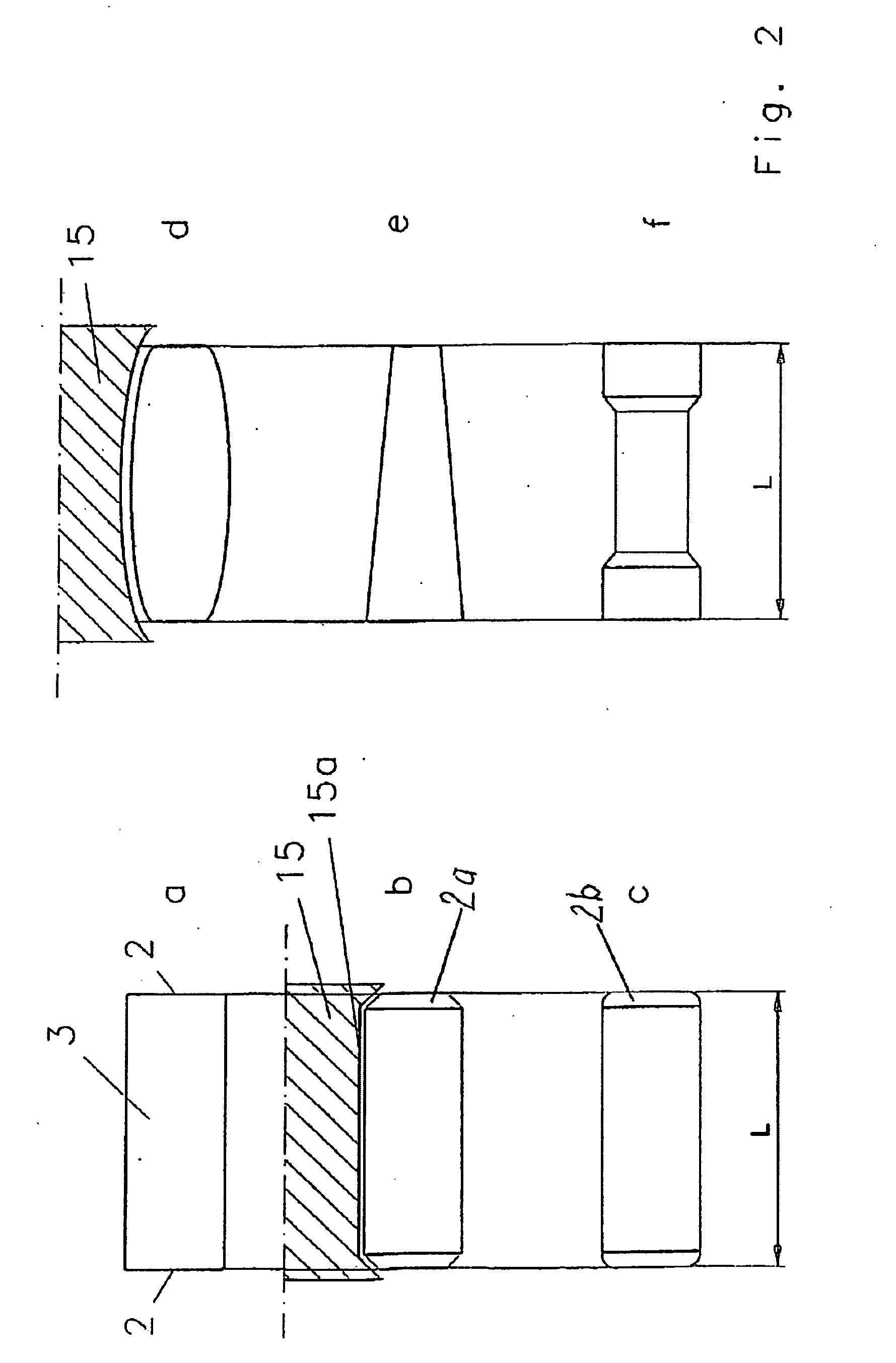
[0025]The above mentioned grinding machines are directed at adjusting the second
grinding wheel of the grinding machine according to the invention to the longitudinal contour of the finished bar-shaped workpiece and can also encompass the chamfers on the face.
Machining of the workpiece faces by the numerically controlled peripheral grinding method based on CX interpolation principles makes it possible to
grind the rounded radii or chamfers on the edges together with the lateral surfaces, without extending the
cycle time. This also applies to chamfers on the face if the contour of the grinding wheel is appropriately chamfered. The chamfers on the face are ground as part of the same clamping, in one contour operation, at the same time as the lateral surfaces and the longitudinally extending chamfers. Rechucking can be dispensed with. In the overall, the process can be controlled with considerably greater ease and reliability, with respect to the required geometric data (dimensional, shape and position tolerances). This not only saves
machining time, but in particular also avoids the risk inaccuracy associated with rechucking. In addition, during trimming, the contour of the grinding wheels can be adjusted with accuracies in the mm range. This produces chamfers on the faces that always have precisely the same widths, across the entire lengths thereof, and relative on one and other. Also in this respect, the invention improves the machining speed and the accuracy of the results.
[0027]A further embodiment relates to a grinding
cell, which is provided with a twin arrangement of two grinding machines according to the invention and a common loading
cell. This further reduces the investment costs and
space requirements, while maintaining the
advantage of feeding only from the front.

