High-Efficiency Thin-Film Solar Cells

a solar cell, high-efficiency technology, applied in the field of photovoltaics and solar cells, can solve the problems of reducing cell quantum efficiency, and flat thin-film crystalline silicon substrates having poor mechanical strength for cell and module processing needs, so as to eliminate or reduce disadvantages and problems, and reduce manufacturing costs

Inactive Publication Date: 2010-07-15
BEAMREACH SOLAR INC
View PDF102 Cites 20 Cited by
  • Summary
  • Abstract
  • Description
  • Claims
  • Application Information

AI Technical Summary

Benefits of technology

[0007]Therefore a need has arisen for fabrication process improvements and manufacturing costs reductions for forming a three-dimensional thin-film solar cell (3-D TFSC). In accordance with the disclosed subject matter, a three-dimensional thin-film solar cell is provided which substantially eliminates or reduces disadvantages and problems associated with previously developed 3-D TFSC.
[0010]Technical advantages of the disclosed subject matter include fabrication process improvements and manufacturing cost reductions by utilizing (111) crystallographic orientation planes to make inverted pyramid cavities on the solar cell substrate. Further, the inverted pyramidal cavities provide increased mechanical rigidity to the 3-D TFSS that is made from the template.
[0011]A technical advantage of the simplified fabrication processes and higher gas-to-silicon conversion ratio of epitaxial growth provided when using a template having inverted pyramidal cavities is an inverted pyramidal cavity based 3-D TFSS provides improved mechanical rigidity and strength. The strength of the template may be adjusted according to the arrays and staggered patterns of inverted pyramidal cavities provided.
[0015](3) Three-dimensional thin-film solar cells disclosed are mechanically robust because of their unique 3D structure, providing enhanced mechanical strength and handle-ability.
[0016]Further technical advantages of the disclosed subject matter include: 1) the semiconductor templates consist of known crystallographic silicon planes, i.e., the (111) and (100) planes and the epitaxial silicon layer grown from these two silicon planes yields better quality than from DRIE etched silicon 3-D surfaces, and 2) the large cavity opening angle (70.6°) of the disclosed silicon template formed by the cavity sidewall (111) planes is much wider than that may be etched from using deep reactive ion etch (DRIE) silicon etch. Therefore, the porous silicon formation, epitaxial silicon growth, and releasing of 3-D TFSS are more practical and cost efficient than a DRIE etched template.

Problems solved by technology

These processes are often costly and difficult.
Also, flat thin-film silicon substrates may have reduced mean optical path length which reduces IR absorption and results in reduced cell quantum efficiency.
And flat thin-film crystalline silicon substrates may have poor mechanical strength for cell and module processing needs.
Micro cracking defects at substrate edges and pinholes defects within the substrate could cause cracking initiations and these cracks propagate easily along the crystallographic directions.

Method used


Image

  • High-Efficiency Thin-Film Solar Cells
  • High-Efficiency Thin-Film Solar Cells
  • High-Efficiency Thin-Film Solar Cells

Examples


Embodiment Construction

[0030]The following description is not to be taken in a limiting sense, but is made for the purpose of describing the general principles of the present disclosure. The scope of the present disclosure should be determined with reference to the claims. Exemplary embodiments of the present disclosure are illustrated in the drawings, like numbers being used to refer to like and corresponding parts of the various drawings.

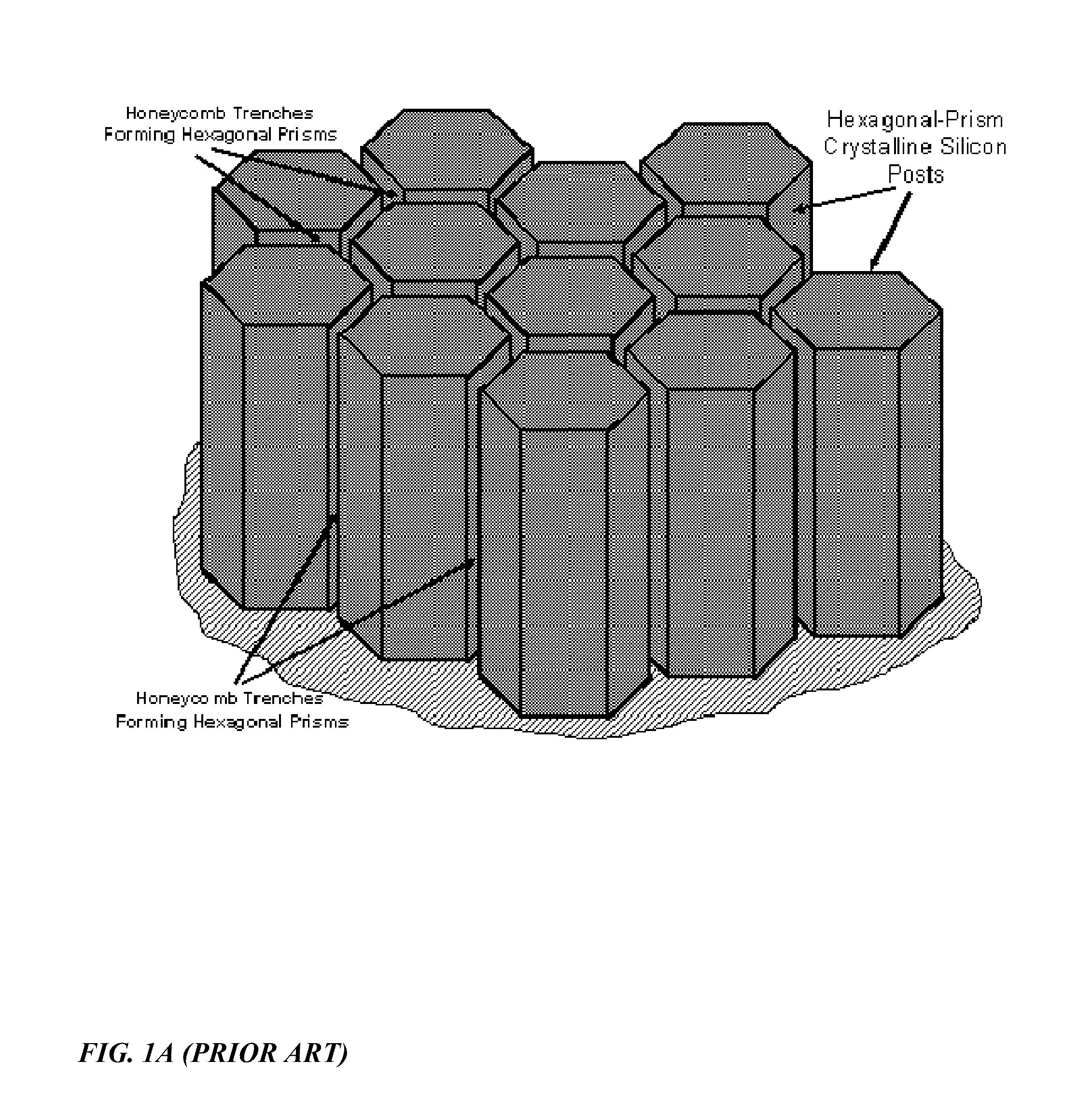
[0031]FIG. 1A illustrates a partial view of a re-usable mono-crystalline silicon template with hexagonal-prism posts disclosed in U.S. Pat. Pub. No. 2008 / 0264477A1. The hexagonal pillars are etched by deep-reactive ion etching (DRIE) with photolithographically patterned photoresist as the hard masking layer. The DRIE etching provides well defined high-aspect ratio gaps between the pillars, however the narrow gaps are difficult to fill by the epitaxial silicon growth and it is difficult to release the epitaxial layer from such a template.

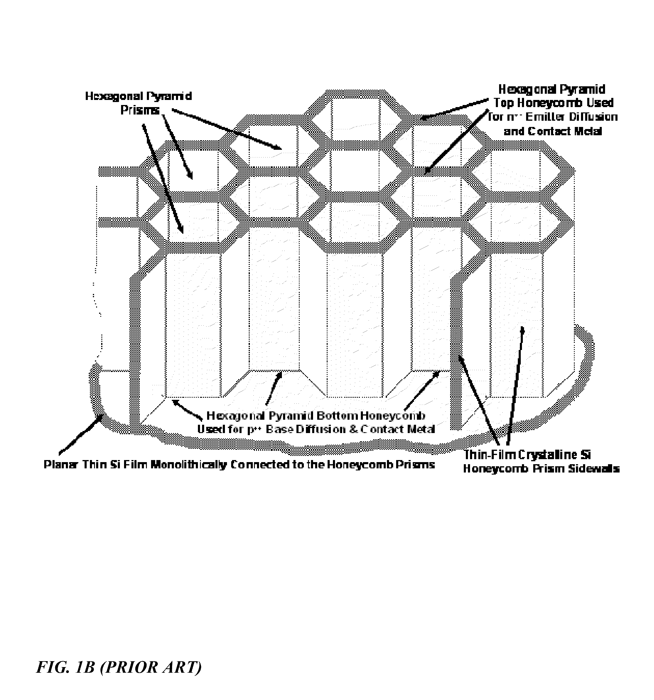
[0032]FIG. 1B illustrates a parti...


PUM


Abstract

A three-dimensional solar cell comprising a semiconductor substrate with an inverted pyramidal cavity, emitter metallization regions on ridges on the surface of the semiconductor substrate which define an opening of the inverted pyramidal cavity, and base metallization regions on a region which form the apex of the inverted pyramidal cavity. A method for fabricating a three-dimensional thin-film solar cell from an inverted pyramidal three-dimensional thin-film silicon substrate by doping ridges on the surface of the semiconductor substrate which define an opening of an inverted pyramidal cavity on the substrate to form an emitter region, and doping a region which forms the apex of the inverted pyramidal cavity to form a base region. Adding a surface passivation layer to the surface of the substrate. Selectively etching the passivation layer from the emitter region and base region. Then concurrently metallizing the emitter region and base region.

Description

[0001]This application claims the benefit of provisional patent application 61 / 114,378 filed on Nov. 13, 2008, which is hereby incorporated by reference.FIELD[0002]This disclosure relates in general to the field of photovoltaics and solar cells, and more particularly to three-dimensional thin-film solar cells and methods for manufacturing three-dimensional thin-film solar cells.DESCRIPTION OF THE RELATED ART[0003]Current methods for manufacturing a three-dimensional thin-film solar cell (3-D TFSC) include forming a 3-Dimensional thin-film silicon substrate (3-D TFSS) using a silicon template. The template may comprise a plurality of posts and a plurality of trenches between said a plurality of posts. The 3-D TFSS may then be formed by forming a sacrificial layer on the template, subsequently depositing a semiconductor layer, selective etching the sacrificial layer and releasing the semiconductor layer from the template. More specifically, the said semiconductor layer is a self-suppo...

Claims


Application Information

Patent Timeline
Patent Type & Authority Applications(United States)
IPC IPC(8): H01L31/0236H01L31/18
CPCH01L31/0236H01L31/035281H01L31/068H01L31/18H01L31/1804Y10T117/1092H01L21/3065H01L29/045H01L29/0657H01L31/02363Y02E10/547H01L31/1892H01L31/022425H01L31/182H01L31/056Y02E10/52Y02E10/546Y02P70/50
Inventor WANG, DAVID XUAN-QIMOSLEHI, MEHRDAD M.
Owner BEAMREACH SOLAR INC
Why Eureka
Try Eureka