Flash memory device with physical cell value deterioration accommodation and methods useful in conjunction therewith

a flash memory and physical cell value technology, applied in the field of flash memory devices, can solve the problems of increasing reducing the reliability of the device, and the detection errors of the measured level during the read operation, so as to increase the bit error rate, increase the density, and enhance the effect of inaccuracy effects

Active Publication Date: 2010-07-15
AVAGO TECH INT SALES PTE LTD
View PDF103 Cites 126 Cited by
  • Summary
  • Abstract
  • Description
  • Claims
  • Application Information

AI Technical Summary

Benefits of technology

[0007]Nowadays, flash memory devices store information with high density on Flash cells with ever-decreasing dimensions. In addition, Multi-Level Cells (MLC) store several bits per cell by setting the amount of charge in the cell. The amount of charge is then measured by a detector, calculated by a threshold voltage of the transistor gate. Due to inaccuracies during the programming procedure and charge loss due to time and temperature (also known as retention), the measured levels during a Read operation suffer from detection errors. The small dimensions of the Flash cells result in cells that can store very small amounts of charge, enhancing the effects of inaccuracies due to programming and retention. Thus, new single level cells (SLC) and Multi-Level Cell (MLC) devices have significantly increased bit error rate (BER), decreasing the reliability of the device.
[0012]In some embodiments, only one set of representative cells is designated for each erase sector, as opposed to embodiments in which each and every page in the erase sector has its own set of representative cells. In the former, per-erase sector embodiments, typically, a reliably stored indicator (“offset cell”) in each page indicates the interval of time which elapsed between the programming of the per-erase sector representative cells and the programming of the page in question, thereby allowing retention time between the programming of a certain page and its reading to be obtained. Alternatively, in certain applications, all pages in each erase sector may be programmed at approximately the same time.

Problems solved by technology

Due to inaccuracies during the programming procedure and charge loss due to time and temperature (also known as retention), the measured levels during a Read operation suffer from detection errors.
Thus, new single level cells (SLC) and Multi-Level Cell (MLC) devices have significantly increased bit error rate (BER), decreasing the reliability of the device.
The higher the number of program-erase cycles, the higher the bit error rate.
Thus, today's Multi-Level Cell(MLC) devices can perform around Np=1000 cycles for 10 year retention before the allocation of 16-32 bytes of redundancy per 512 bytes of data bytes becomes insufficient to correct errors.
Following Np program-erase cycles the device is still operational but the bit error rate is higher.
Using a single decoding scheme may result in poor read performance (read time and power consumption).
The ECC complexity may be designed for the end of life conditions and may force higher complexity decoding for pages that are more reliable or at the beginning of life.

Method used


Image

  • Flash memory device with physical cell value deterioration accommodation and methods useful in conjunction therewith
  • Flash memory device with physical cell value deterioration accommodation and methods useful in conjunction therewith
  • Flash memory device with physical cell value deterioration accommodation and methods useful in conjunction therewith

Examples


Embodiment Construction

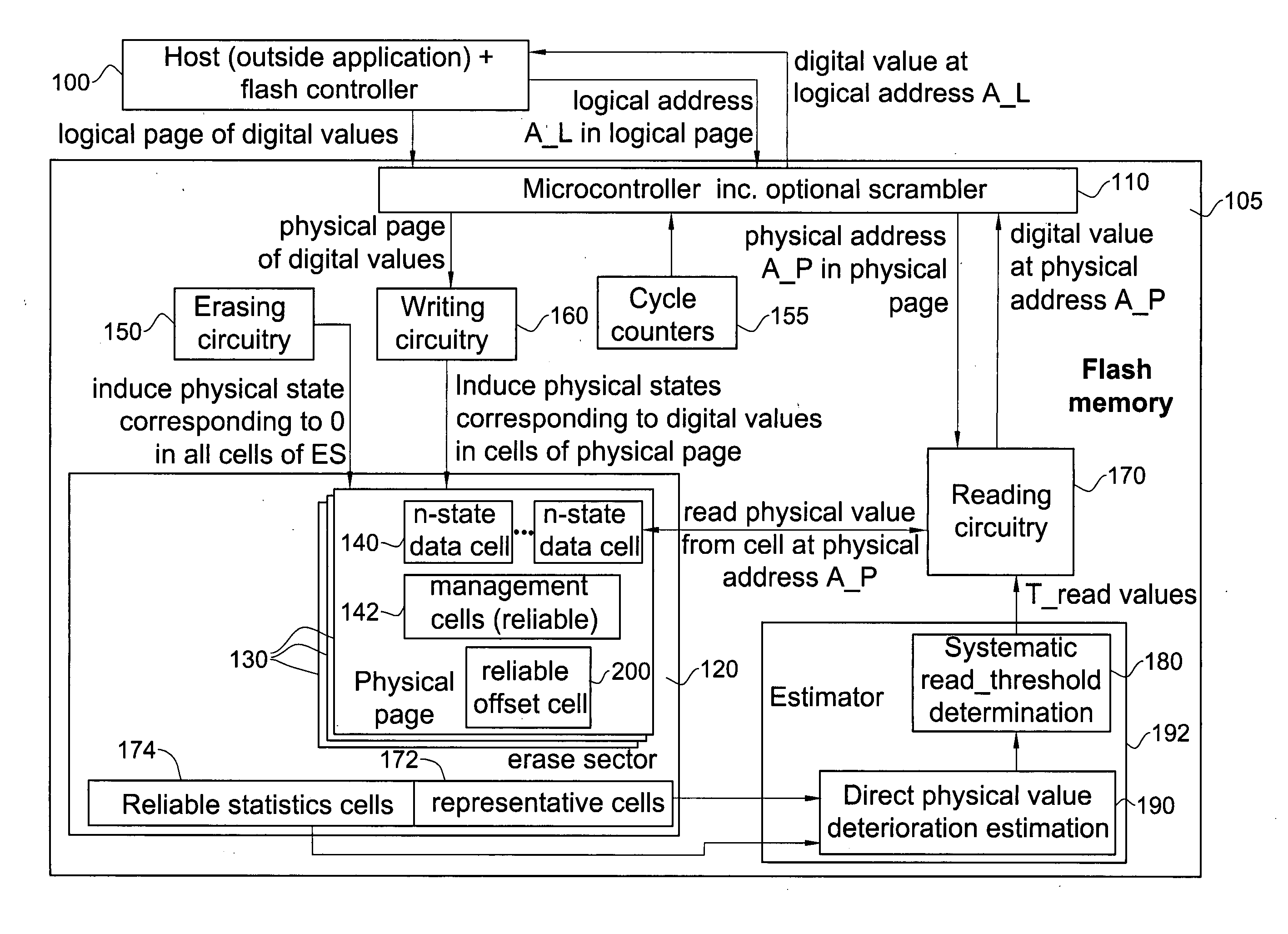
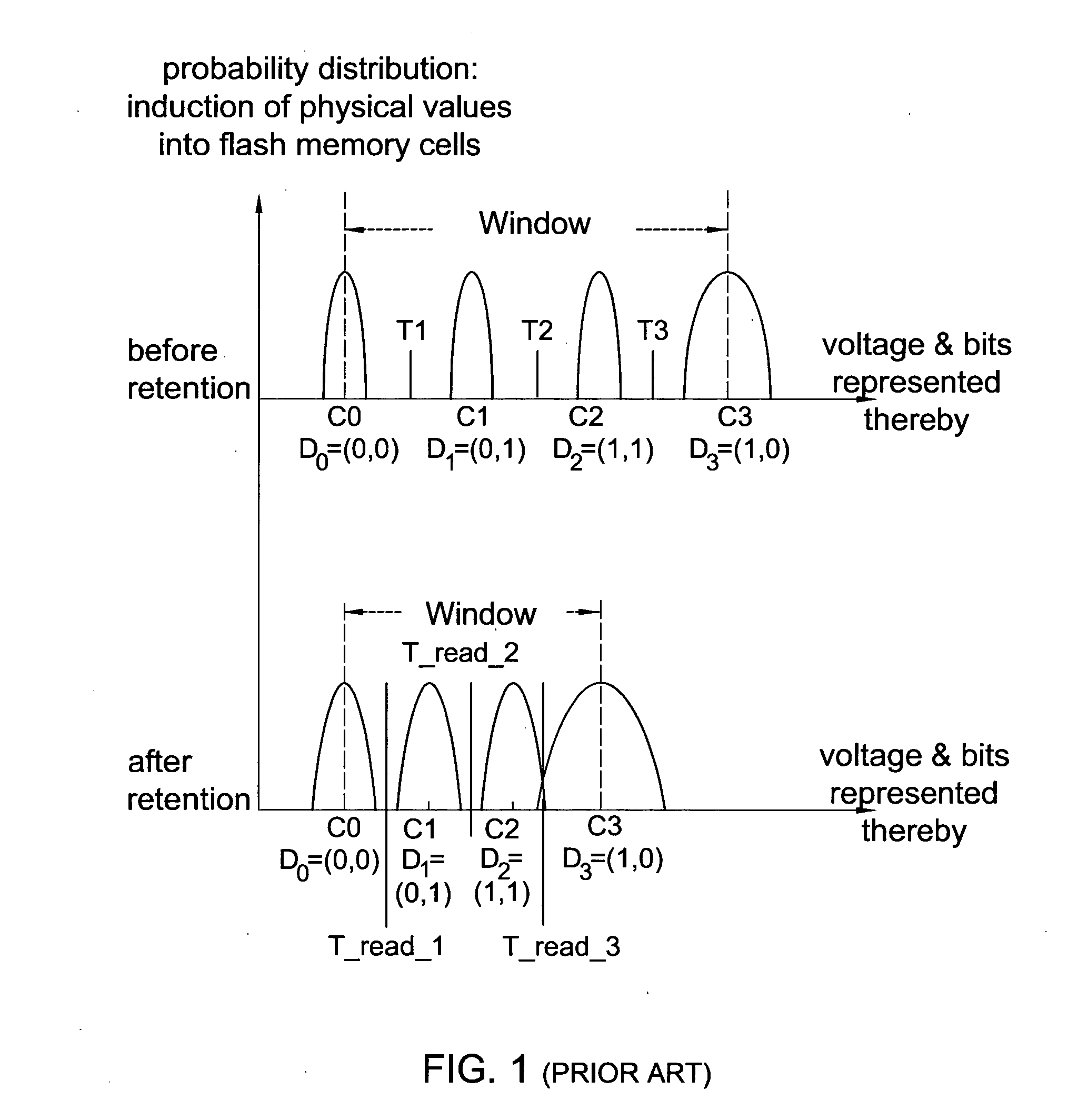
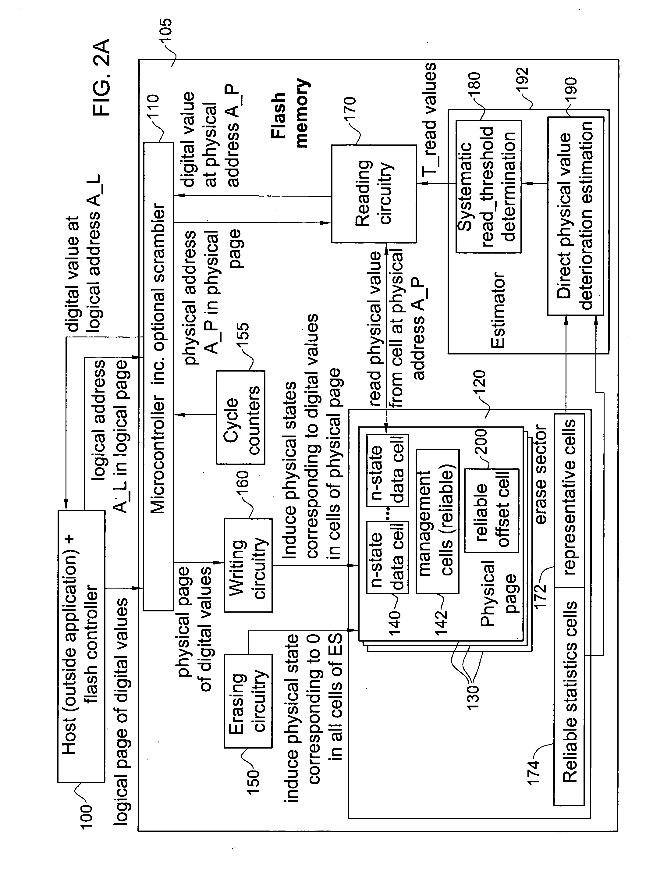
[0077]Reference is now made to FIG. 1 which is a graph (top) of manufacturer-defined initial cell voltage distributions, which apply to a flash memory device which has yet to undergo cycling and retention vs. a graph (bottom) of cell voltage distributions which apply to a flash memory device which has undergone cycling and retention.

[0078]A read threshold, T* (also termed herein T_read) is used to distinguish between each two adjacent programming charge levels. Generally these two charge levels comprise physical values clustering normally around a first charge C_1, and physical values clustering normally around a second charge level C_2.

[0079]As described in detail below, T_read may be computed by dedicating a first subset of the representative cells, comprising at least one and typically several representative cells, to storing C_1. A second subset of the representative cells, comprising at least one and typically several representative cells is dedicated to storing C_2. These two ...


PUM


Abstract

A method for determining thresholds useful for converting cell physical levels into cell logical values in an array of digital memory cells storing physical levels which diminish over time, the method comprising determining extent of deterioration of the physical levels and determining thresholds accordingly for at least an individual cell in said array; and reading the individual cell including reading a physical level in the cell and converting the physical level into a logical value using the thresholds, wherein the determining comprises storing predefined physical levels rather than data-determined physical levels in each of a plurality of cells and computing extent of deterioration by determining deterioration of the predefined physical levels.

Description

REFERENCE TO CO-PENDING APPLICATIONS[0001]Priority is claimed from the following co-pending applications: U.S. Provisional Application No. 60 / 996,782, filed Dec. 5, 2007 and entitled “Systems and Methods for Using a Training Sequence in Flash Memory”, U.S. Provisional Application No. 61 / 064,853, filed Mar. 31, 2008 and entitled “Flash Memory Device with Physical Cell Value Deterioration Accommodation and Methods Useful in Conjunction Therewith”, U.S. Provisional Application No. 61 / 006,805, filed Jan. 31, 2008 and entitled “A Method for Extending the Life of Flash Devices”, U.S. Provisional Application No. 61 / 071,465, filed Apr. 30, 2008 and entitled “Systems and Methods for Temporarily Retiring Memory Portions” and U.S. Provisional Application No. 61 / 129,608, filed Jul. 8, 2008 and entitled “A Method for Acquiring and Tracking Detection Thresholds in Flash Devices”.[0002]Other co-pending applications include: U.S. Provisional Application No. 60 / 960,207, filed Sep. 20, 2007 and entit...

Claims


Application Information

Patent Timeline
Patent Type & Authority Applications(United States)
IPC IPC(8): G06F12/00G06F12/02
CPCG06F12/0246G11C16/349G06F2212/1032
Inventor WEINGARTEN, HANANLEVY, SHMUELKATZ, MICHAEL
Owner AVAGO TECH INT SALES PTE LTD
Why Eureka
Try Eureka