Rotor blade for a rotary wing aircraft

Inactive Publication Date: 2010-07-22
EUROCOPTER DEUT GMBH
View PDF28 Cites 12 Cited by
  • Summary
  • Abstract
  • Description
  • Claims
  • Application Information

AI Technical Summary

Problems solved by technology

They generate noise and vibrations that can be perceived, for example, in the cabin of the rotary wing aircraft and thus adversely affect the comfort of the passengers.
Moreover, these vibrations are disadvantageous with respect to service life and maintenance, since they can lead to material fatigue of components and continued relative motion of the components with the accompanying wear and tear.
Complex aeromechanical and aeroelastic phenomena, for example the collision of a rotor blade with blade vortices of one leading rotor blade at a

Method used


Image

  • Rotor blade for a rotary wing aircraft
  • Rotor blade for a rotary wing aircraft
  • Rotor blade for a rotary wing aircraft

Examples


Embodiment Construction

[0009]On this basis, the object of the invention is to provide a rotor blade with a rotor blade flap that has a mechanically and kinematically simple structure, has favorable aerodynamic properties, enables continuously gradual deformation in the profile chord and span direction, and has reduced elongation of centrifugal force on the actuators.

[0010]This object is achieved by the features of claim 1.

[0011]The dependent claims form advantageous developments of the invention.

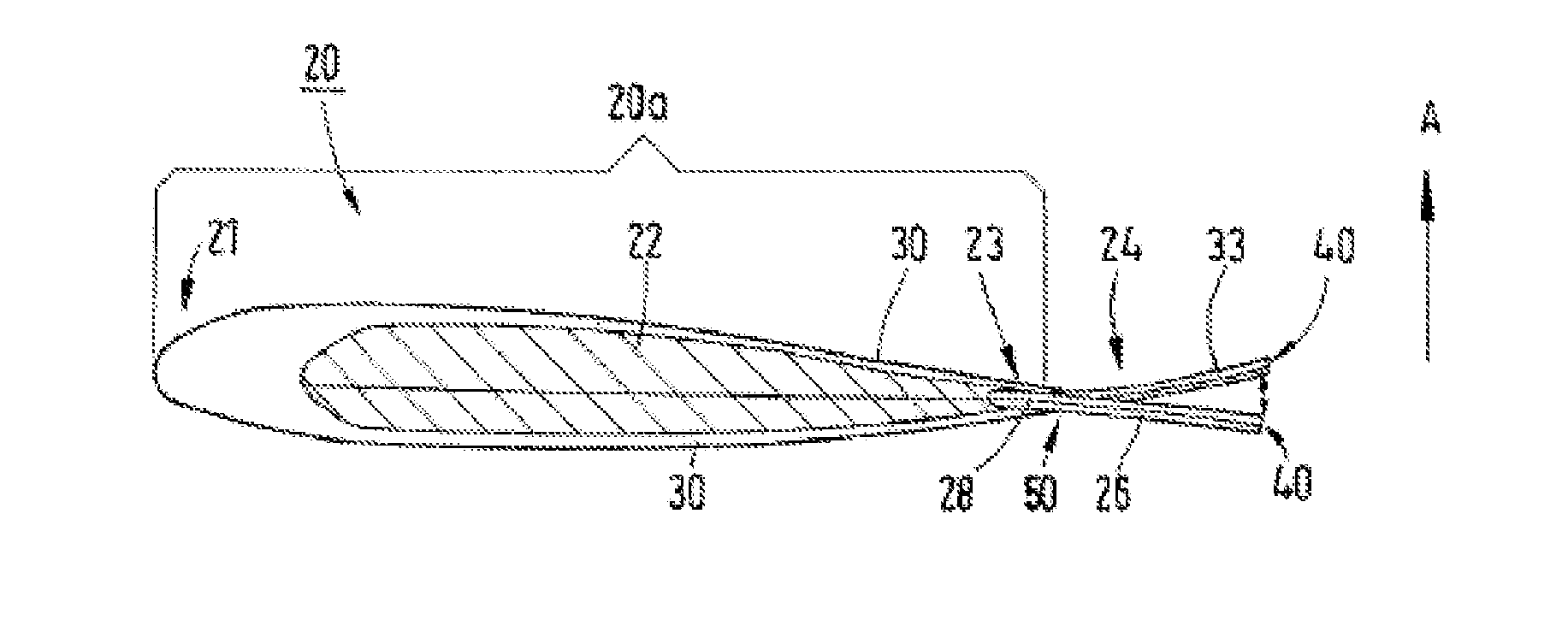
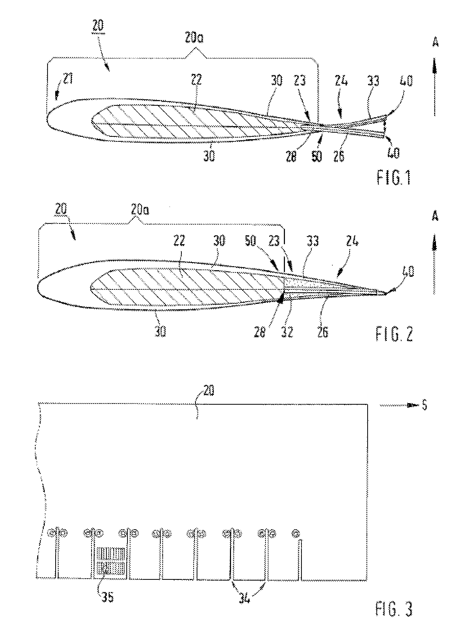
[0012]The rotor blade according to the invention, especially for a rotary wing aircraft, comprises an aerodynamically effective rotor blade profile with a profile nose region, a profile base body with a profile core, and an upper and lower cover skin that envelops the profile core, as well as a profile rear edge region with a rear edge. A reversibly bendable supporting member is attached with the first end to an end region of the profile base body pointing toward the rear edge and projects with a second end freely...


PUM


Abstract

The invention relates to a rotor blade (20), especially for a rotary wing aircraft. The invention is characterized in that an aerodynamically effective rotor blade profile with a profile nose region (21), a profile base body (20a) with a profile core, an upper and lower cover skin (30) that envelops the profile core (22), and a profile rear edge region (23) with a rear edge (40) and a reversibly bendable supporting member (26) that can be attached with the first end to the end region of the profile base body (20a) pointing toward the rear edge (40) and projects with the second end freely out of the profile base body (20a) and its end region toward the rear edge (40) and forms a movable rotor blade flap (24), and several actuators (35) that are dynamically connected to the projecting second end of the reversibly bendable supporting member (26) and an arc-shaped flap deflection can be initiated via the change in length of the actuators, the second end of the reversibly bendable supporting member (26) that forms the rotor blade flap (24) viewed in the direction of the span (S) being divided by notches (34) into several segments to which at least one actuator (35) at a time is assigned.

Description

TECHNICAL DOMAIN[0001]This invention relates to a rotor blade with a movable rotor blade flap, especially for a rotary wing aircraft, such as for example a helicopter, and a rotary wing aircraft with such a rotor blade.PRIOR ART[0002]Air vortices form in operation on the rotor blades of a rotary wing aircraft. They generate noise and vibrations that can be perceived, for example, in the cabin of the rotary wing aircraft and thus adversely affect the comfort of the passengers. Moreover, these vibrations are disadvantageous with respect to service life and maintenance, since they can lead to material fatigue of components and continued relative motion of the components with the accompanying wear and tear.[0003]Complex aeromechanical and aeroelastic phenomena, for example the collision of a rotor blade with blade vortices of one leading rotor blade at a time and the resulting forces acting on the rotor blade, are the cause of this noise and these vibrations. In order to take into accou...

Claims


Application Information

Patent Timeline
IPC IPC(8): B64C27/00B64C11/04
CPCB64C27/473Y02T50/34B64C2027/7283B64C27/615Y02T50/30
Inventor ALTMIKUS, ANDREEBAUER, MARKUSGROHMANN, BORISMANGELSDORF, STEPHANMAUCHER, CHRISTOPHPFALLER, RUPERTAHCI, ELIF
Owner EUROCOPTER DEUT GMBH
Why Eureka
Try Eureka